Machine tool with built-in motor

A technology for machine tools and lathes, which is applied to the field of machine tools with motors in the middle, can solve the problems affecting the concentricity of the motor spindle, the rotation of the motor spindle, and the long distance, and achieve the effects of convenient limit, improved concentricity, and easy adjustment.

Inactive Publication Date: 2020-11-24
台州市航工机床有限公司
View PDF6 Cites 0 Cited by
  • Summary
  • Abstract
  • Description
  • Claims
  • Application Information

AI Technical Summary

Problems solved by technology

[0004] However, due to the long distance between the main motor of the machine tool and the spindle box, when the main motor is working, the belt connecting the output end of the main motor and the main shaft of the machine tool will vibrate during the transmission process, causing the motor shaft to rotate. The situation of shaking, thus affecting the concentricity of the motor shaft

Method used


Image

  • Machine tool with built-in motor
  • Machine tool with built-in motor
  • Machine tool with built-in motor

Examples


Embodiment

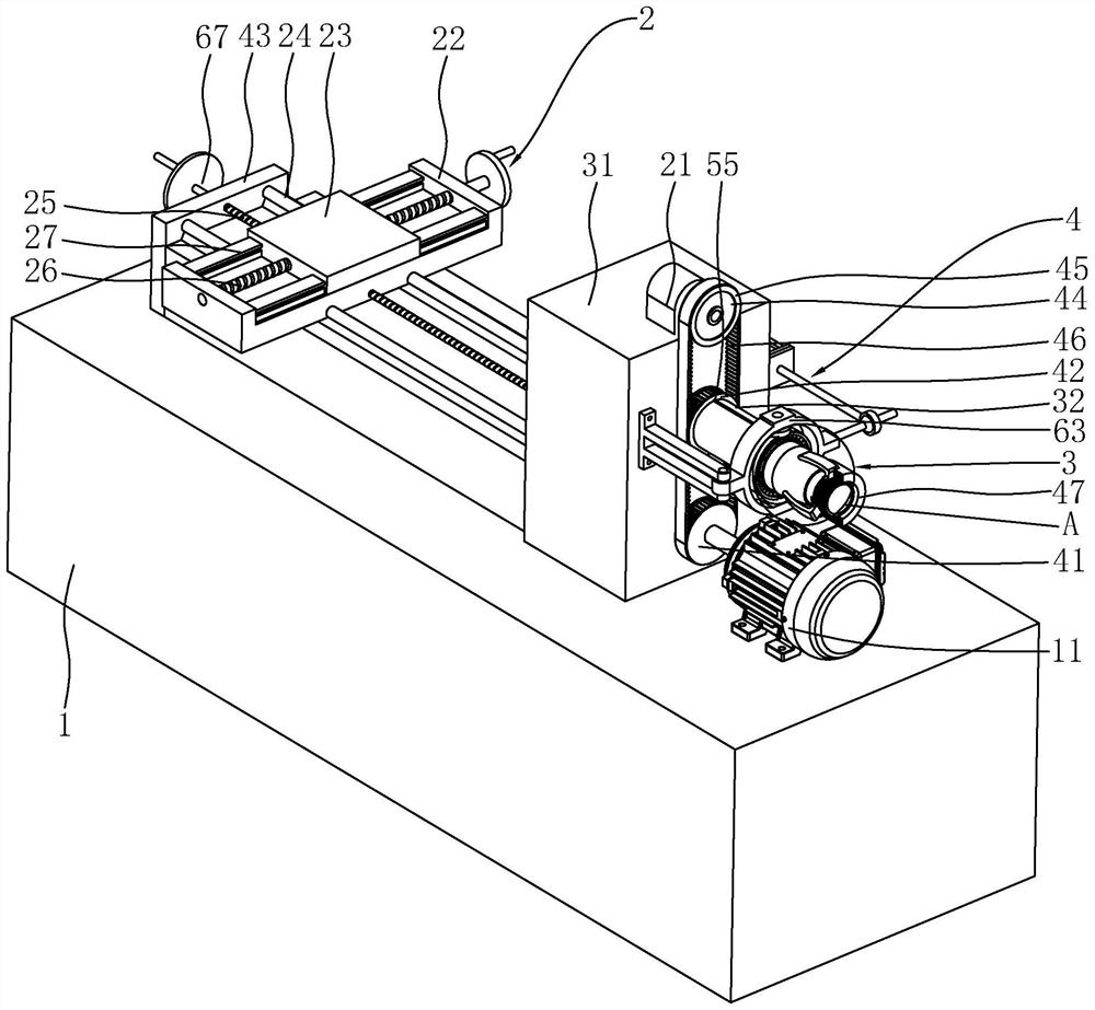
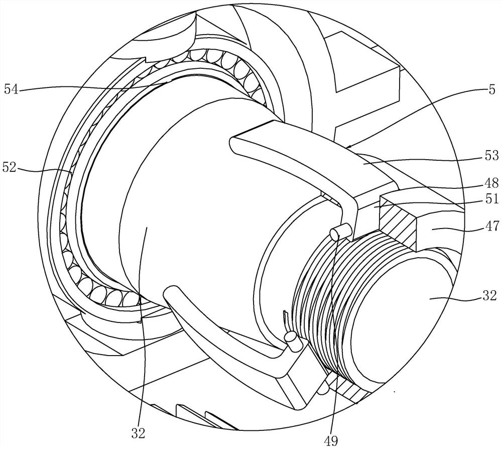
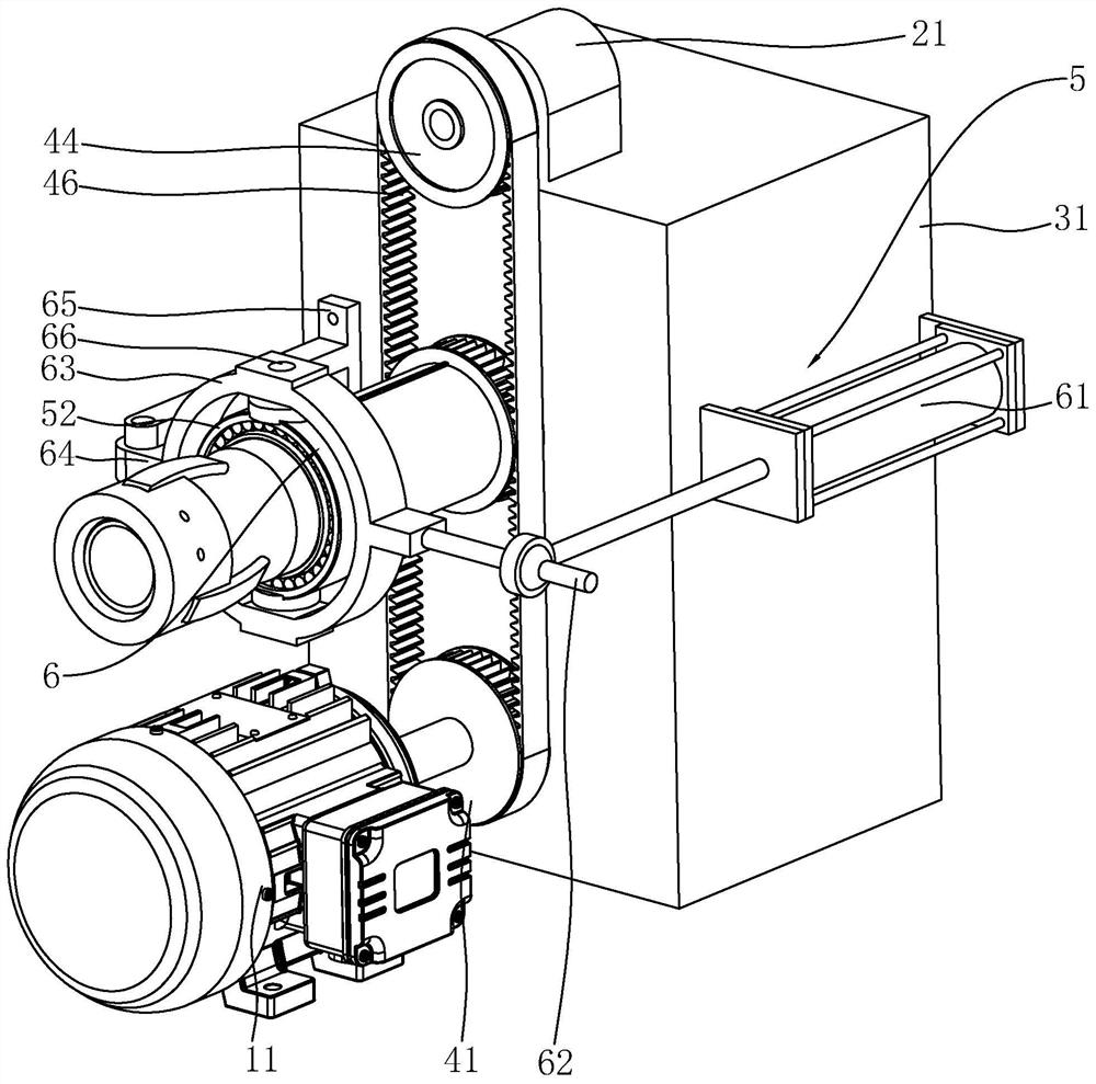
[0032] Embodiment: a kind of machine tool with motor in the middle, such as figure 1 and figure 2 As shown, it includes a base 1 , a motor 11 fixed on the top of the base 1 , and a lathe mechanism 2 and a fixing device 3 arranged on the top of the base 1 . The fixing device 3 includes a fixed platform 31 fixed on the top of the base 1, a fixed tube 32 rotatably mounted on the side of the fixed platform 31 close to the motor 11, and a transmission mechanism arranged between the fixed tube 32 and the motor 11 for driving the fixed tube 32 to rotate 4. The transmission mechanism 4 includes a drive pulley 41 fixed on the output end of the motor 11, a drive pulley 42 fixed on the outer peripheral surface of the fixed pipe 32, a mounting table 21 fixed on the top of the fixed table 31, and a rotation mounted on the side of the mounting table 21 near the fixed pipe 32. An encoder 44, a driven pulley 45 fixed on the outer peripheral surface of the encoder 44, and a toothed belt 46 ...


PUM


Abstract

The invention discloses a machine tool with a built-in motor, and relates to the technical field of machine tools. The machine tool is characterized by comprising a base, a motor, a lathe mechanism and a fixing device, wherein the motor is fixed at the top of the base, and the lathe mechanism and the fixing device are arranged at the top of the base; the fixing device comprises a fixing table, a fixing pipe and a transmission mechanism, wherein the fixing table is fixed to the top of the base, the fixing pipe is rotationally installed on the side, close to the motor, of the fixing table, and the transmission mechanism is arranged between the fixing pipe and the motor and used for driving the fixing pipe to rotate; a fixing cover is in threaded connection with the end, away from the fixingtable, of the fixing pipe; three mounting through holes are uniformly distributed in the peripheral surface of the fixing cover in the circumferential direction of the fixing cover; rotating shafts are rotationally installed on the opposite inner sides of the mounting through holes correspondingly, and abutting parts are fixed to the opposite ends of the two adjacent rotating shafts; and an abutting mechanism used for driving the corresponding abutting part to rotate towards the side close to the fixing pipe is arranged between each abutting part and the fixing pipe. According to the machine tool with the built-in motor, the problem that the concentricity of the main shaft of the motor is influenced is solved, and the effect of improving the concentricity of the fixing pipe during rotationis achieved.

Description

technical field [0001] The invention relates to the technical field of machine tools, more specifically, it relates to a machine tool with a central motor. Background technique [0002] At present, parts with higher precision requirements and finer surface roughness requirements generally need to be finalized by cutting on machine tools. [0003] The prior art can refer to the Chinese invention patent application whose publication number is CN107838680A, which discloses a single-motor locomotive-drilling compound machine tool, including the front leg of the lathe, the main motor arranged in the front leg of the lathe, and the motor fixed on the top of the front leg of the lathe. A lathe headstock and a lathe spindle rotatably mounted in the lathe headstock. The output end of the main motor and the main shaft of the lathe are driven by a belt. The spindle of the lathe is driven by the main motor to process the workpiece. [0004] However, due to the long distance between t...

Claims


Application Information

Patent Timeline
Patent Type & Authority Applications(China)
IPC IPC(8): B23P23/02B23Q3/08B23Q5/28
CPCB23P23/02B23Q3/08B23Q5/28
Inventor 鄢文舟
Owner 台州市航工机床有限公司
Why Eureka
Try Eureka