
Laser cladding method for valve plate and valve seat in valve

A laser cladding and valve plate technology, which is applied in the coating and metal material coating process, etc., can solve the problems of insufficient bonding force, peeling of the coating and the base material, and the inability of the coating and the base material to form a firm metallurgical bond. , to achieve the effect of strong hardness and wear resistance, increasing the amount of addition

Inactive Publication Date: 2020-11-17
南京派纳克激光科技有限公司
View PDF0 Cites 0 Cited by
  • Summary
  • Abstract
  • Description
  • Claims
  • Application Information

AI Technical Summary

Problems solved by technology

In this process, the base material (valve plate or seat) itself is hardly melted, which leads to the inability to form a firm metallurgical bond between the coating and the base material (valve plate or seat), and the bonding force is not strong enough. When the thickness of the coating exceeds 0.3mm, the residual stress generated by the thermal action during the spraying process tends to exceed the bonding force of the gas between the coating and the base material, resulting in peeling between the coating and the base material, so thermal spraying is used Neither nor plasma spraying can achieve thicker coatings
[0005] In addition, because the molten powder is blown onto the surface of the base material, the gas mixed in the molten powder will be covered in the coating to form pores, so thermal spraying and plasma spraying usually cannot obtain a completely dense coating

Method used


Image

  • Laser cladding method for valve plate and valve seat in valve
  • Laser cladding method for valve plate and valve seat in valve
  • Laser cladding method for valve plate and valve seat in valve

Examples


preparation example Construction

[0039] Step 1. Preparation of semi-finished products: by mechanical processing and other means, the blanks are processed into semi-finished products according to the drawings of the valve plate and valve seat, and the semi-finished products are reserved for the size of the parts that need laser cladding and additives.

[0040] Step 2. Visual inspection or contact inspection: put the semi-finished product into the area to be processed in the laser cladding system and fix it, and then use sensors such as cameras or contact probes to detect the position, length, width, Height, straight and circular hole boundaries.

[0041]Step 3. Path generation: The valve plate is arranged in parallel lines of single-layer multi-lane or multi-layer multi-lane according to plane cladding to generate a walking path for laser cladding; the valve seat generates a path in the form of a ring or a spiral line, and finally cover the entire plane;

[0042] Step 4. Laser cladding: Set the process parame...

Embodiment 1

[0061] This embodiment provides a laser cladding method for a valve plate and a valve seat in a valve, which includes the following steps:

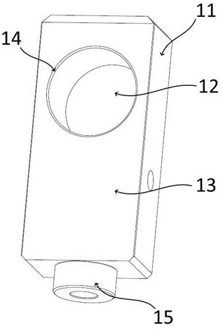
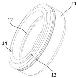
[0062] Step 1. Preparation of semi-finished products: by mechanical processing, according to the drawings of the valve plate and valve seat, the blank is processed into figure 2 , 3 The semi-finished product shown, and the semi-finished product is reserved for the size of the part that needs laser cladding and additives.

[0063] Step 2. Visual inspection or contact inspection: put the semi-finished product into the area to be processed in the laser cladding system and fix it, and then use sensors such as cameras or contact probes to detect the position, length, width, Height, straight and circular hole boundaries.

[0064] Step 3. Path generation: The valve plate is arranged in parallel lines of single-layer multi-lane or multi-layer multi-lane according to plane cladding to generate a walking path for laser cladding; the valve seat g...

Embodiment 1-2~ Embodiment 1-7

[0068] On the basis of Example 1, the ratio of the iron-based powder is adjusted, and its specific ratio and related mechanical performance test data are shown in the table below (wear resistance: at a test pressure of 240N / reciprocating frequency of 2Hz, the test time 2h, detect the amount of wear loss of the cladding layer).

[0069]


PUM


Abstract

The invention discloses a laser cladding method for a valve plate and a valve seat in a valve, and belongs to the technical field of laser processing and manufacturing. The method comprises the stepsthat step 1, a semi-finished product is prepared; step 2, visual detection or contact detection is performed; step 3, a path is generated; step 4, laser cladding is performed; and step 5, machining isconducted. Sealing surfaces of the valve plate and the valve seat are subjected to surface treatment through a laser coating technology, and sealing coating which is compact in structure, resistant to abrasion and corrosion and high in thickness is obtained. Through compounding and optimization, an optimal proportion of Cr, Ni and Fe is obtained, a Cr-Fe alloy phase is formed, and the surface ofthe Cr-Fe alloy phase has higher hardness and abrasion resistance. Walking pause time is set at a chamfer, so that an addition amount of cladding powder is increased, and the problems of melting and collapsing of a base material under a high-temperature condition in the cladding process are avoided.

Description

technical field [0001] The invention belongs to the technical field of laser processing and manufacturing, in particular to a laser cladding method for a valve plate and a valve seat in a valve. Background technique [0002] At present, in the manufacturing and repairing process of valve plates and valve seats, the surface wear-resistant and corrosion-resistant layer processing is basically based on plasma spraying or flame spraying. Plasma spraying is usually automated, and the metal powder is melted and sprayed onto the surface of the valve plate or valve seat through a plasma flame to obtain high hardness and good wear and corrosion resistance. Flame spraying is usually done by hand. The workpiece is preheated by a high-temperature flame gun, and then the metal powder is melted and sprayed onto the surface of the valve plate or seat. [0003] The valve plate and the valve seat are used together to interact and rub against each other to play the role of sealing the switch...

Claims


Application Information

Patent Timeline
IPC IPC(8): C23C24/10C22C38/40
CPCC22C38/40C23C24/103
Inventor 沈鸿源李延民丁龙凤王鑫波朱广江徐志强
Owner 南京派纳克激光科技有限公司
Learn More