
Broadband high-linearity low-noise driving amplifier of 5G base station

A driving amplifier, high linearity technology, applied in amplifiers, amplifier protection circuit layout, improving amplifiers to expand bandwidth, etc., can solve the problem that low power consumption and linearity are not well compatible, and there is no high-power signal discharge channel , can not be well compatible and other issues, to achieve good harmonic suppression function, good anti-burnout characteristics, low insertion loss effect

Active Publication Date: 2020-11-13
CHENGDU GANIDE TECH
View PDF9 Cites 5 Cited by
  • Summary
  • Abstract
  • Description
  • Claims
  • Application Information

AI Technical Summary

Problems solved by technology

[0003] (1) Low power consumption, high gain, and low noise amplification indicators restrict each other: driven by the market, the standby power consumption of the RF front-end receiver needs to be reduced as much as possible to achieve energy-saving functions, but the traditional common source (or common emitter) In amplifier design, the best noise bias point to achieve optimal noise, and the bias point that satisfies the maximum gain and transconductance often cannot achieve the lowest power consumption of the amplifier, so the two indicators are not well compatible
[0004] (2) Low power consumption and high linearity index mutually restrict each other: in traditional common source (or common emitter) amplifier design, high linearity index needs to select amplifier transistors with high power capacity and high 1dB compression point under a fixed process, while high Power capacity often requires a large DC power consumption, so low power consumption and linearity are not well compatible
[0005] In addition, typical high-linearity and low-noise drive amplifiers do not have high-power signal discharge channels, and there is a risk of high-power burnout in the front-end application of 5G base stations

Method used


Image

  • Broadband high-linearity low-noise driving amplifier of 5G base station
  • Broadband high-linearity low-noise driving amplifier of 5G base station

Examples


Embodiment Construction

[0027] Exemplary embodiments of the present invention will now be described in detail with reference to the accompanying drawings. It should be understood that the implementations shown and described in the drawings are only exemplary, intended to explain the principle and spirit of the present invention, rather than limit the scope of the present invention.

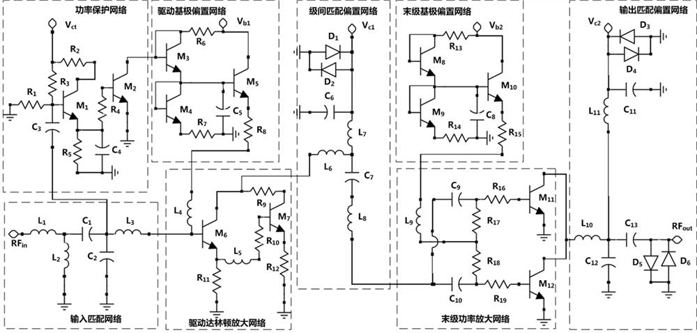
[0028] An embodiment of the present invention provides a broadband high-linearity low-noise driving amplifier for a 5G base station, such as figure 1 As shown, including input matching network, power protection network, driving Darlington amplifying network, driving base bias network, interstage matching bias network, final stage power amplification network, final stage base bias network and output matching bias network configure the network.

[0029] The input end of the input matching network is used as the radio frequency input end of the broadband high linearity low noise driving amplifier, and its output end is con...


PUM


Abstract

The invention discloses a broadband high-linearity low-noise driving amplifier of a 5G base station. The driving amplifier comprises an input matching network, a power protection network, a driving Darlington amplification network, a driving base bias network, an inter-stage matching bias network, a final-stage power amplification network, a final-stage base bias network and an output matching bias network. The broadband, high-linearity and low-noise driving amplifier structure capable of being applied to the 5G base station is realized by utilizing a multistage amplification network technology. According to the invention, a Darlington tube is used as a driving amplification network, the driving bandwidth of the amplifier is remarkably improved, the noise coefficient is reduced, and the power protection network is adopted, so that the driving amplifier has the good anti-burning characteristic, and the whole amplifier has the advantages of being high in linearity, high in gain, low in noise and the like in combination with the last-stage high-linearity power amplification network.

Description

technical field [0001] The invention belongs to the technical field of 5G communication and integrated circuits, and in particular relates to the design of a broadband high-linearity low-noise drive amplifier for a 5G base station. Background technique [0002] With the rapid development of the 5G civil communication market, RF front-end receivers are also developing in the direction of high performance, high integration, and low power consumption. Therefore, the market urgently needs ultra-wideband, high gain, high linearity, low power consumption, and low noise RF and microwave driver amplifier chips. However, there are always some design problems in the current traditional RF and microwave driver amplifier chip design, mainly reflected in: [0003] (1) Low power consumption, high gain, and low noise amplification indicators are mutually restricted: driven by the market, the standby power consumption of the RF front-end receiver needs to be reduced as much as possible to ...

Claims


Application Information

Patent Timeline
Patent Type & Authority Applications(China)
IPC IPC(8): H03F1/26H03F1/42H03F1/32H03F1/02H03F1/52H03F1/56H03F1/30
CPCH03F1/0205H03F1/26H03F1/302H03F1/32H03F1/42H03F1/52H03F1/565
Inventor 王测天邬海峰覃良吕继平胡柳林童伟陈依军
Owner CHENGDU GANIDE TECH
Learn More