Stripping and conveying device for two ends of connecting wire

A technology for conveying devices and connecting wires, which is applied in the direction of connection, line/collector parts, electrical components, etc., can solve problems that affect the production and processing effect, complicate the production and processing steps, and reduce the use effect of equipment, so as to facilitate the realization and structure Simple, program-friendly effects

Pending Publication Date: 2020-11-13
温州盛世机车业有限公司
View PDF0 Cites 0 Cited by
  • Summary
  • Abstract
  • Description
  • Claims
  • Application Information

AI Technical Summary

Problems solved by technology

[0002] Motor vehicles or electric vehicles are usually equipped with a control circuit board in the handlebar. The integrated switch on the handlebar realizes the control of mechanisms such as lights, horns, and turn signals. The integrated switch, control circuit board, and electrical appliances are connected by wires. Connection, the length of these wires is short, and the ends of the wires need to be connected to the terminal structure to adapt to the installation. At present, the production and processing steps of these wires are relatively complicated. It is necessary to cut the wires of appropriate length from the rolled wires first, and then connect the two ends of the wires. Peeling exposes the internal metal wires. Tighten and bundle the scattered metal wires at one end, and use the other end for terminal connection. The current equipment can only perform peeling operations, which cannot be effectively tightened and bundled, reducing the use effect of the equipment. In addition, the truncation and peeling of the existing equipment is usually completed by independent equipment, and then the terminal is transferred and installed, resulting in low processing efficiency, affecting the production and processing effect, and causing a waste of manpower

Method used


Image

  • Stripping and conveying device for two ends of connecting wire
  • Stripping and conveying device for two ends of connecting wire
  • Stripping and conveying device for two ends of connecting wire

Examples


Embodiment Construction

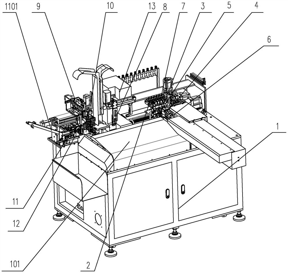
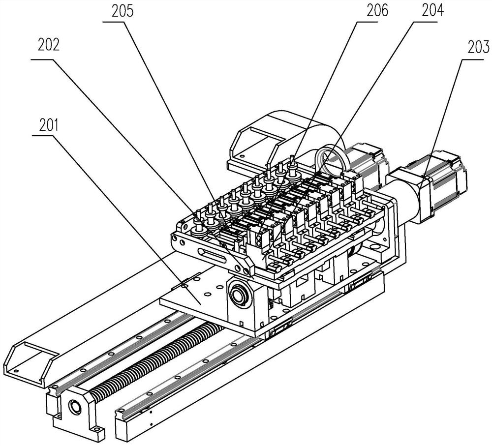
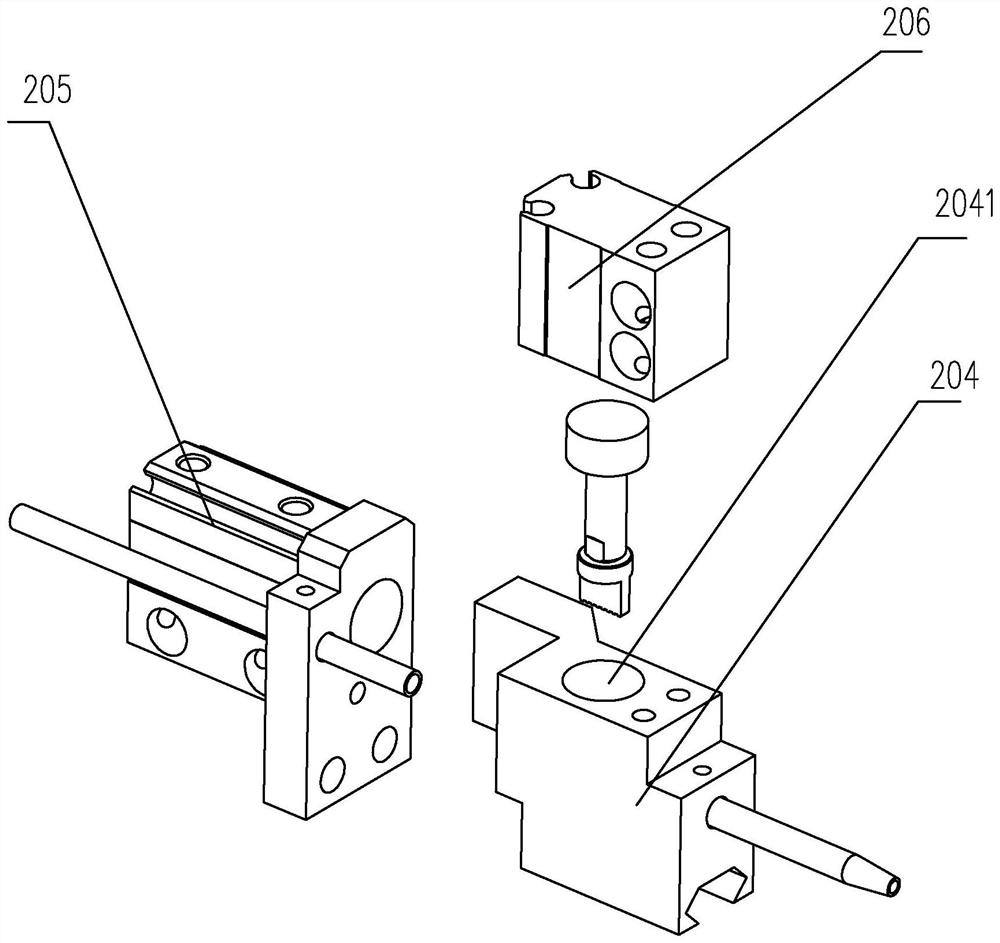
[0036] The embodiment of the stripping conveying device at both ends of the connecting wire of the present invention is for example Figure 1 to Figure 12 As shown: including a frame 1, the frame 1 is sequentially provided with a feeding mechanism 2, a terminal installation mechanism 13, a positioning seat 10, a loading support 12 and a feeding track 1101, and the corresponding feeding mechanism 1101 is on the frame 1 The position of the mechanism 2 is provided with a cutting knife seat 305, a ring cutter seat 303, a stripping knife seat 307, a lift frame 3 and a cutting cylinder 301 for driving the lift frame 3 to lift, and the lift frame 3 is provided with a ring cutter 302, a cutting knife 304 and a stripping knife 306, a ring cutting channel is formed between the ring cutting knife 302 and the ring cutting knife seat 303, a cutting channel is formed between the cutting knife 304 and the cutting knife seat 305, A stripping channel is formed between the stripping knife 306 a...


PUM


Abstract

The invention discloses a stripping and conveying device for two ends of a connecting wire. The device comprises a rack, a traction seat, a suction seat, a feeding mechanism and a terminal mounting mechanism, wherein the feeding mechanism is arranged on one side of the rack, a girdling channel, a cut-off channel and a stripping channel are formed on the rack, a suction pipe is arranged on the suction seat, a bundling piece is rotationally arranged on the suction seat, an air guide channel is formed in the bundling piece, the suction pipe is communicated with the girdling channel through the air guide channel, a traction clamp is arranged on the traction seat, the rack is provided with a conveying slide rail between the terminal mounting mechanism and the traction seat, a conveying seat isarranged on the conveying slide rail, and a conveying clamp used for clamping a cut wire and feeding the wire into the stripping channel to be stripped and subsequently conveyed is arranged on the conveying seat. The device is simple and reasonable in structure, can be used for stripping the end parts of a wire and tightening and bundling the wire, and is convenient for subsequent processing and use.

Description

technical field [0001] The invention relates to the technical field of processing equipment for motor vehicle parts, in particular to a device for peeling and conveying both ends of a connecting wire. Background technique [0002] Motor vehicles or electric vehicles are usually equipped with a control circuit board in the handlebar. The integrated switch on the handlebar realizes the control of mechanisms such as lights, horns, and turn signals. The integrated switch, control circuit board, and electrical appliances are connected by wires. Connection, the length of these wires is short, and the ends of the wires need to be connected to the terminal structure to adapt to the installation. At present, the production and processing steps of these wires are relatively complicated. It is necessary to cut the wires of appropriate length from the rolled wires first, and then connect the two ends of the wires. Peeling exposes the internal metal wires. Tighten and bundle the scattere...

Claims


Application Information

Patent Timeline
IPC IPC(8): H01R43/28
CPCH01R43/28
Inventor 林样弟黄安平林世铰张世见董建全
Owner 温州盛世机车业有限公司
Why Eureka
Try Eureka