Eureka AIR delivers breakthrough ideas for toughest innovation challenges, trusted by R&D personnel around the world.

Integrated PtCu/carbon nanofiber catalyst layer, preparation method thereof and application thereof in fuel cell

A carbon nanofiber and catalytic layer technology, applied in nanotechnology, nanotechnology, battery electrodes, etc., can solve the problems of poor uniformity of the fuel cell catalytic layer and low assembly efficiency of membrane electrodes, and achieve good catalyst uniformity and load stability. High sex, favorable effect of exposure

Active Publication Date: 2020-11-10
CENT SOUTH UNIV
View PDF11 Cites 3 Cited by
  • Summary
  • Abstract
  • Description
  • Claims
  • Application Information

AI Technical Summary

Problems solved by technology

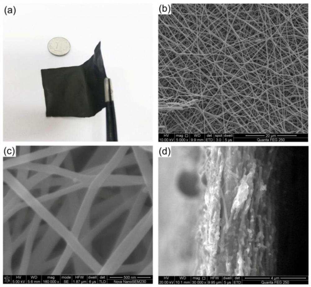
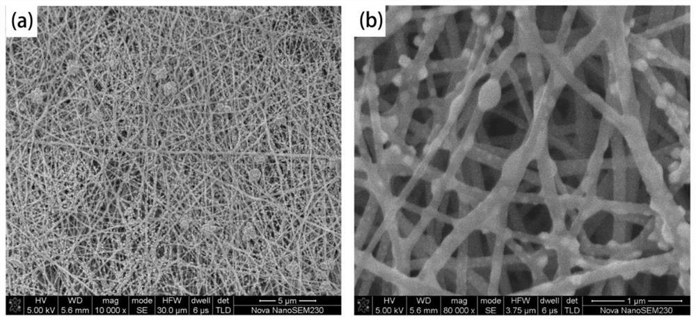
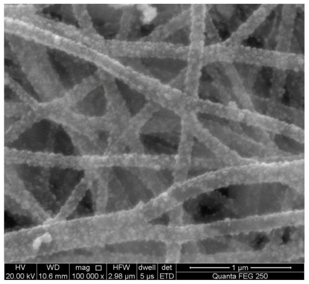
[0005] In view of the poor uniformity of the fuel cell catalytic layer prepared by the existing spraying method, the low efficiency of membrane electrode assembly and the powder removal caused by traditional carbon powder as the carrier of the catalytic layer, the first purpose of the present invention is to provide a stable An integrated PtCu / nano-carbon fiber catalytic layer with good performance, large specific surface area and high catalytic activity

Method used


Image

  • Integrated PtCu/carbon nanofiber catalyst layer, preparation method thereof and application thereof in fuel cell
  • Integrated PtCu/carbon nanofiber catalyst layer, preparation method thereof and application thereof in fuel cell
  • Integrated PtCu/carbon nanofiber catalyst layer, preparation method thereof and application thereof in fuel cell

Examples


Embodiment 1

[0062] 1. Preparation of electrospinning precursor body fluid

[0063]Weigh 150mg of boric acid and slowly add it to 13.35g of N,N-dimethylformamide solvent (DMF), stir for 10min, obtain a transparent solution after fully dissolving, weigh polyacrylonitrile (PAN, MW=90000), slowly Added to the above transparent solution, stirred for 6 hours to fully dissolve to obtain a viscous and transparent electrospinning precursor liquid; the mass fraction of boric acid in the boron source is 1 wt%, and the mass fraction of PAN in the polymer carbon source is 10 wt%.

[0064] 2. Electrospinning

[0065] Inject the electrospinning precursor fluid obtained in Step 1 into a plastic syringe with a stainless steel needle, and put the syringe into the electrospinning inner frame with a step-by-step propulsion device. The stainless steel needle is connected to the positive pole of the DC high-voltage power supply, and the steel A constant DC voltage was applied between the needle and the ground...

Embodiment 2

[0084] 1. Preparation of electrospinning precursor body fluid

[0085] Weigh 100g of boric acid and slowly add it to 8.9kg of N,N-dimethylformamide solvent (DMF), stir for 30min, obtain a transparent solution after fully dissolving, weigh polyacrylonitrile (PAN, MW=90000), slowly Add to the above transparent solution, stir for 12 hours to fully dissolve to obtain a viscous and transparent electrospinning precursor liquid; the mass fraction of boric acid in the boron source is 1 wt%, and the mass fraction of PAN in the polymer carbon source is 10 wt%.

[0086] 2. Electrospinning

[0087] Put the electrospinning precursor solution obtained in step 1 into the solution tank, and connect the conductive wire to the positive electrode. A constant DC voltage is applied between the receiving devices, and the tape-carrying receiving device receives composite nanofibers. The conductive thread is made of wear-resistant conductive material, the solution feeding speed is 100mL / h, the cons...


PUM

PropertyMeasurementUnit
pore sizeaaaaaaaaaa
diameteraaaaaaaaaa

Abstract

The invention discloses an integrated PtCu / carbon nanofiber catalyst layer, a preparation method thereof and an application thereof in a fuel cell. The preparation method of the integrated PtCu / carbonnanofiber catalyst layer comprises the following steps: obtaining a nano polymer fiber membrane through electrostatic spinning, carrying out heat treatment on the nano polymer fiber membrane to obtain a carbon nanofiber membrane, depositing copper nanocrystals on the carbon nanofiber membrane through a pulse electrodeposition method, alloying the copper nanocrystals through an in-situ replacementmethod, and obtaining a PtCu alloy / carbon nanofiber film; soaking the PtCu alloy / carbon nanofiber film in a perfluorosulfonic acid resin solution, and adhering the PtCu alloy / carbon nanofiber film toa proton exchange membrane for mould pressing and curing to obtain the PtCu / carbon nanofiber catalyst layer. The preparation method has the advantages of being efficient, low in cost and environmentally friendly, the obtained integrated PtCu / carbon nanofiber catalyst layer is high in catalytic activity and good in stability, the problems of falling and uniformity of materials in the using processcan be avoided, and meanwhile the membrane electrode assembling efficiency is improved.

Description

technical field [0001] The present invention relates to a fuel cell catalytic material, in particular to an integrated PtCu / nano-carbon fiber catalytic layer material and a method for preparing an integrated PtCu / nano-carbon fiber catalytic layer material by means of electrospinning, pulse electrodeposition, and displacement reduction. The application of the integrated PtCu / nano carbon fiber catalytic layer material as a fuel cell catalytic layer belongs to the field of fuel cell catalysis. Background technique [0002] In recent years, with the rapid development of the global economy, the growing demand for energy will force us to develop clean and sustainable new energy, and the development of the fuel cell field has opened up a new direction for renewable energy. Proton Exchange Membrane Fuel Cell (PEMFC) is a device that directly converts chemical energy into electrical energy, which can achieve zero pollution and zero emissions in the true sense. Compared with the widel...

Claims


Application Information

Patent Timeline
Patent Type & Authority Applications(China)
IPC IPC(8): H01M4/92C25D5/18C25D3/38B22F9/24B82Y30/00B82Y40/00
CPCH01M4/921H01M4/926C25D5/18B22F9/24C25D3/38B82Y30/00B82Y40/00Y02E60/50
Inventor 梁伊丽李振溱谢志勇
Owner CENT SOUTH UNIV
Why Eureka
Eureka Blog
Learn More