Method and system for full gas cooling of secondary cooling section of continuous casting

A secondary cooling and gas cooling technology, which is applied in the field of continuous casting in the metallurgical industry, can solve the problems of poor working environment in the secondary cooling section, reduced metal yield, and uneven surface temperature of the slab, so as to improve the cooling efficiency of continuous casting and Continuous casting slab quality, avoiding slab surface oxidation and uneven cooling, and eliminating the effect of high temperature slab surface oxidation

Active Publication Date: 2021-10-22
UNIV OF SCI & TECH BEIJING
View PDF0 Cites 2 Cited by
  • Summary
  • Abstract
  • Description
  • Claims
  • Application Information

AI Technical Summary

Problems solved by technology

But this method has the following problems: 1. The water mist falling on the surface of the high-temperature slab is affected by gravity, and it is difficult to distribute evenly on the surface of the high-temperature slab, resulting in uneven temperature on the surface of the slab, and then producing solidification cracks or other due to temperature differences. Both cause solidification defects and deteriorate the quality of the slab; 2. The water mist falling on the surface of the high-temperature slab forms a "liquid film" on the surface of the slab, which reduces the heat transfer efficiency; 3. The water mist cooling method causes the surface of the high-temperature slab to form The oxide layer deteriorates the surface quality of the slab, which is not conducive to the monitoring of the surface of the high-temperature slab during the production process, and reduces the metal yield; 4. The water mist cooling method consumes a lot of water and cannot be recycled, which wastes water resources; 5. The water mist cooling method Poor working environment in the secondary cooling section
6. The billet heat absorbed by the water mist cooling method cannot be recovered, resulting in energy waste

Method used


Image

  • Method and system for full gas cooling of secondary cooling section of continuous casting
  • Method and system for full gas cooling of secondary cooling section of continuous casting
  • Method and system for full gas cooling of secondary cooling section of continuous casting

Examples


Embodiment 1

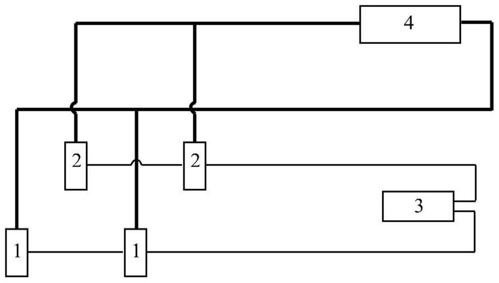
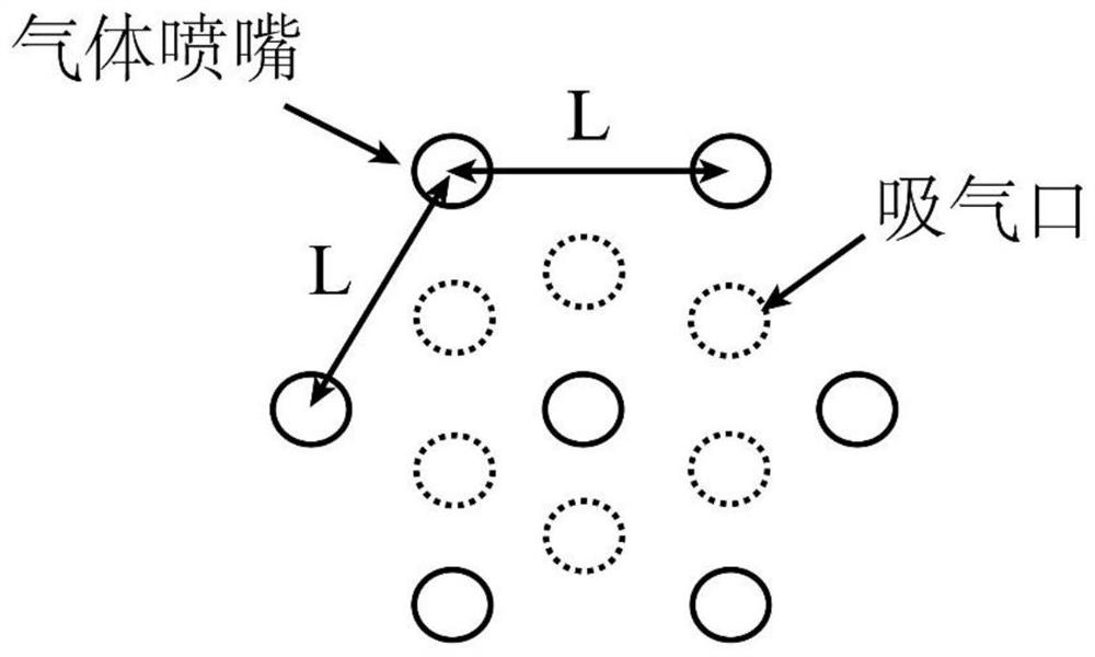
[0057] refer to figure 2 and image 3 , In this embodiment, a 150×150mm billet with Q235 steel as an example is used to introduce a method and system for full gas cooling in the secondary cooling section of continuous casting.

[0058] The method is as figure 2 As shown, the thick solid line is the cooling gas passage, and the thin solid line is the cooling medium passage. The direction of the suction port is consistent with that of the gas nozzle. The cooling gas is argon, which is sprayed from the gas nozzle to the surface of the slab, and the heat released by the solidification of the slab is taken away by forced convection heat exchange and radiation heat exchange, and then the argon is recovered from the suction port and sent to the cooling equipment It is cooled, and after the temperature of the argon gas drops to 25±5°C, it is sent to the nozzle for recycling. In this embodiment, the cooling medium is water. The arrangement of gas nozzles in this embodiment is sh...

Embodiment 2

[0091] refer to figure 2 and image 3 , In this embodiment, a 280 × 325mm bloom, casting steel 42CrMo, as an example to introduce a method and system of full gas cooling in the secondary cooling section of continuous casting.

[0092] The method is as figure 2 As shown, the thick solid line is the cooling gas passage, and the thin solid line is the cooling medium passage. The direction of the suction port is consistent with that of the nozzle. The cooling gas is argon, which is injected from the nozzle to the surface of the slab, and the heat released by the solidification of the slab is taken away by forced convection heat exchange and radiation heat exchange, and then the argon is recovered from the suction port and sent to the cooling equipment It is cooled, and the argon gas temperature drops to 25±5°C, and then it is sent to the nozzle for recycling. In this embodiment, the cooling medium is water. The arrangement of gas nozzles in this embodiment is shown in ima...

Embodiment 3

[0125] refer to figure 2 and image 3 , in this embodiment, a 220 × 1800mm slab, cast steel as Q235B, as an example to introduce a method and system of full gas cooling in the secondary cooling section of continuous casting.

[0126] The method is as figure 2 As shown, the thick solid line is the cooling gas passage, and the thin solid line is the cooling medium passage. The direction of the suction port is consistent with that of the gas nozzle. The cooling gas is argon, which is injected from the gas nozzle to the surface of the slab, and the heat released by the solidification of the slab is taken away by forced convection heat exchange and radiation heat exchange, and then the argon is recovered by the suction port and sent to the cooling equipment It is cooled, and after the temperature of the argon gas drops to 25±5°C, it is sent to the gas nozzle for recycling. In this embodiment, the cooling medium is water. The top view of the arrangement of gas nozzles in this...


PUM


Abstract

The invention relates to a method for full gas cooling of the secondary cooling section of continuous casting. The method uses gas that does not undergo oxidation reaction with the high-temperature slab, and the gas is sprayed to the secondary cooling section of continuous casting at a certain speed through a gas nozzle. On the surface of the high-temperature slab, forced convective heat transfer and radiation heat transfer occur on the surface of the high-temperature slab to realize solidification and cooling of the high-temperature slab. According to the difference in pouring steel type, slab casting speed, molten steel superheat and high-temperature slab surface temperature, the flow rate of cooling gas ejected from the gas nozzle is adjusted accordingly to realize the process of dynamic gas distribution in the secondary cooling section of continuous casting. The cooling gas used in the method is recovered by an air suction port and cooled by a gas cooling device, and the cooled cooling gas is delivered to a gas nozzle to realize recycling of the cooling gas. The invention eliminates the oxidation problem of the billet surface in the secondary cooling section of continuous casting, improves the cooling uniformity of the billet and increases the heat exchange efficiency.

Description

technical field [0001] The invention belongs to the field of continuous casting in the metallurgical industry, and in particular relates to a method and system for full gas cooling of a secondary cooling section of continuous casting. Background technique [0002] The high-temperature liquid steel forms a solidified slab shell in the mold of the continuous casting machine, and then enters the secondary cooling section of the continuous casting to continue to solidify. The traditional continuous casting secondary cooling section adopts the water mist cooling method, that is, water mist is sprayed on the surface of the high-temperature slab, and the water mist falling on the surface of the high-temperature slab evaporates and absorbs heat to take away the heat of the high-temperature slab, so as to realize the cooling and cooling of the high-temperature slab. solidification. But this method has the following problems: 1. The water mist falling on the surface of the high-tempe...

Claims


Application Information

Patent Timeline
Patent Type & Authority Patents(China)
IPC IPC(8): B22D11/124B22D11/22
CPCB22D11/1245B22D11/225
Inventor 包燕平华承健
Owner UNIV OF SCI & TECH BEIJING
Why Eureka
Try Eureka