Method for determining catalyst coating and ash distribution on automobile particulate matter catcher

A particle trap and catalyst coating technology, which is used in material analysis, instruments, and measurement devices using wave/particle radiation, and can solve problems such as accumulated ash shedding, complex pore structure, and inability to use

Active Publication Date: 2020-11-06
昆明贵研催化剂有限责任公司
View PDF7 Cites 2 Cited by
  • Summary
  • Abstract
  • Description
  • Claims
  • Application Information

AI Technical Summary

Problems solved by technology

However, there is currently a lack of a fast, intuitive, reliable, and simple method for analyzing catalyst coatings and accumulated ash on automotive particulate matter traps, which seriously restricts the research and development progress of automotive particulate matter trap products, and also limits the development of automotive particulate matter traps to a certain extent. Engineering and industrial application of trap products
[0003] Different from traditional automotive catalysts, automotive particulate traps have a relatively complex pore structure, and the conventional cold mounting method cannot fill the internal pores well, resulting in the destruction of the catalyst coating structure and the accumulation of ash during the sample grinding process. fall off
In addition, the carrier of the automotive particulate filter is cordierite or silicon carbide, both of which are composed of light elements, while the catalyst coating of the automotive particulate filter usually contains a large amount of light elements such as aluminum and oxygen, and the accumulated ash also contains A large amount of light elements such as phosphorus and calcium cannot be used to accurately identify the carrier components, catalyst coatings and accumulated ash of the automotive particulate filter by electron microscopic morphology analysis technology

Method used


Image

  • Method for determining catalyst coating and ash distribution on automobile particulate matter catcher
  • Method for determining catalyst coating and ash distribution on automobile particulate matter catcher
  • Method for determining catalyst coating and ash distribution on automobile particulate matter catcher

Examples


Embodiment 1

[0030] Example 1: A method for measuring the catalyst coating and ash distribution on the automotive particulate filter

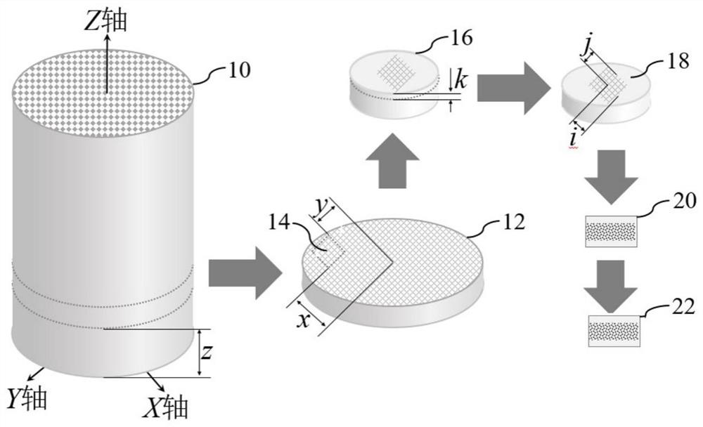
[0031] see figure 1 , the steps included in this embodiment are specifically as follows:

[0032] (1) Marking and sampling

[0033] The origin O is the center of the air intake end face of the automotive particle filter 10, the X-axis passes through the origin on the air intake end face and along the arrangement direction of the quadrangular prism hole array, and the X-axis passes through the origin on the air intake end face and is perpendicular to the X-axis. On the Y axis, the ray pointing from the origin to the gas outlet along the quadrangular prism channel is the positive direction of the Z axis.

[0034] Define the side of the intercepted sample parallel to and close to the YOZ coordinate plane as the first side, the distance between the first side and the YOZ coordinate plane is x, and the distance between the center of the analysis area and the f...

Embodiment 2

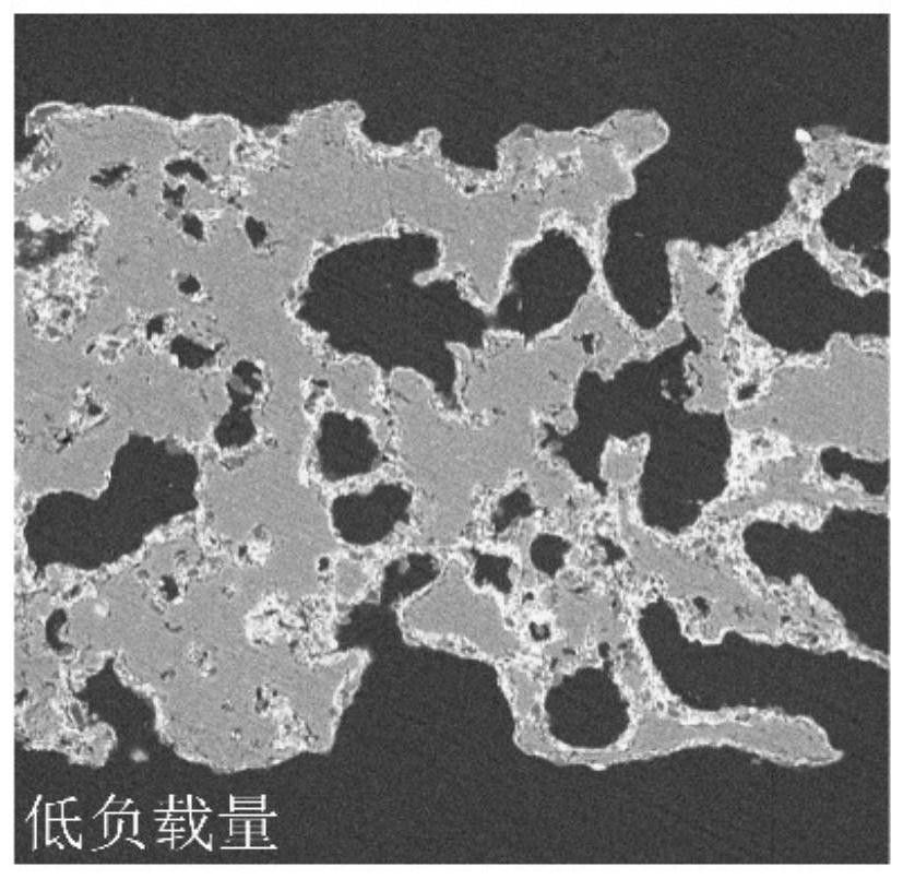
[0047] Example 2: Analysis of Rare Earth Oxide Coating Distribution

[0048] This embodiment includes the following steps:

[0049] Select 2 automotive particulate matter traps with the same catalyst coating, containing rare earth composite oxides, and different loads, and cut cube samples at (-25, 30, 20) spatial positions as described in the steps of Example 1, and try The sample side length is 8mm. Weigh 20 grams of the vacuum-free clear cold mounting set whose main component is epoxy resin and 10 grams of curing agent into the same disposable paper cup, stir thoroughly with a bamboo stick, and pour it into two 12 mm diameter cups after standing for 5 minutes , in a rubber mold with a depth of 12 mm. Put the two intercepted samples vertically into the rubber mold to ensure that the quadrangular prism channels are completely filled with resin, and take out the cold-mounted samples after standing for 80 minutes.

[0050] Choose 180-mesh water sandpaper, and the grinding di...

Embodiment 3

[0053] Example 3: Aluminum Oxide Coating Distribution

[0054] This embodiment includes the following steps:

[0055] Select an automobile particulate filter containing aluminum oxide coating, and cut cube samples at (40,-20,50) spatial positions according to the steps of Example 1, and the side length of the sample is 6 mm. Weigh 10 grams of the vacuum-free clear cold mounting set whose main component is epoxy resin and 5 grams of curing agent into the same disposable paper cup, stir thoroughly with a bamboo skewer, let it stand for 3 minutes, pour it into a 10 mm diameter, deep for 10 mm rubber molds. Put the intercepted sample vertically into the rubber mold to ensure that the quadrangular prism channels are completely filled with resin, and take out the cold-mounted sample after standing for 60 minutes.

[0056] Use 200-mesh water sandpaper, and the grinding disc rotates at 400 rpm, and grind the grinding surface of the cold-mounted sample until it is smooth, and measure...


PUM


Abstract

The invention discloses a method for determining catalyst coating and ash distribution on an automobile particulate matter catcher, and belongs to the technical field of physical property determination of automobile exhaust purification devices. The determination method comprises the following implementation steps: (1), marking and sampling three-dimensional coordinates; (2), filling a quadrangular pore passage of a sample by a vacuumizing-free cold embedding method; (3), preparing a sample which can be observed by a scanning electron microscope; (4), analyzing the morphology and chemical element surface distribution of the polished surface of the sample; and (5), carrying out image layer superposition processing. The determination method provided by the invention has the advantages of rapidness, intuition, reliability, simplicity, convenience and the like, is mainly applied to qualitative analysis of axial and radial spatial distribution conditions of the catalyst coating and accumulated ash on the automobile particulate filter, and has very important significance for accelerating research, development and application of automobile particulate filter products.

Description

technical field [0001] The invention relates to a method for measuring catalyst coating and ash content distribution on an automobile particle trap, and belongs to the technical field of measuring physical properties of automobile tail gas purification devices. Background technique [0002] The promulgation of China's sixth-stage automobile emission regulations, which have been implemented nationwide in different regions and phases, has driven the rapid development of new automotive exhaust purification devices represented by gasoline vehicle particulate traps and diesel vehicle particulate traps. with application. However, there is currently a lack of a fast, intuitive, reliable, and simple method for analyzing catalyst coatings and accumulated ash on automotive particulate matter traps, which seriously restricts the research and development progress of automotive particulate matter trap products, and also limits the development of automotive particulate matter traps to a c...

Claims


Application Information

Patent Timeline
Patent Type & Authority Applications(China)
IPC IPC(8): G01N23/2005G01N23/20091G01N23/203G01N23/2202G01N23/2251
CPCG01N23/2005G01N23/203G01N23/20091G01N23/2251G01N23/2202G01N2223/053G01N2223/1016G01N2223/102G01N2223/61G01N2223/635Y02T10/40
Inventor 王成雄赵云昆杨冬霞夏文正郭律袁新波赵德鹏贺小昆
Owner 昆明贵研催化剂有限责任公司
Why Eureka
Try Eureka