
A three-dimensional multi-beam laser parameter control method and system

A laser parameter, multi-beam technology, used in lasers, laser parts, phonon exciters, etc., can solve the problems of limited multi-beam, low flexibility, low laser processing efficiency, etc., to eliminate manufacturing and installation errors, reduce The effect of small optical system error and improved laser utilization

Active Publication Date: 2021-03-30
WUHAN JINDUN LASER TECH CO LTD
View PDF5 Cites 0 Cited by
  • Summary
  • Abstract
  • Description
  • Claims
  • Application Information

AI Technical Summary

Problems solved by technology

Since the patent application does not involve multi-beam parallel processing, its control method does not involve individual regulation of the position and energy of each laser beam in the multi-beam
Moreover, the CCD camera is one of the area array detectors. This patent application is the same as the patent with the publication number CN109079318B, and there is a problem that the real-time energy information of each laser beam in the multi-beam cannot be obtained.
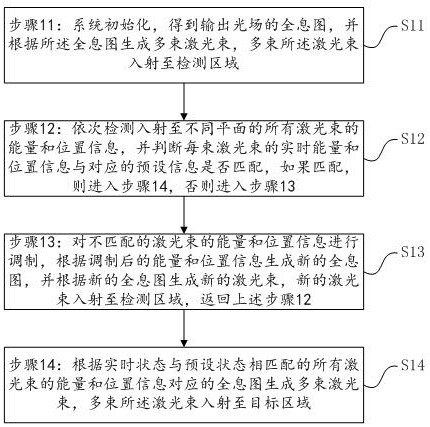
[0008] It can be seen that the prior art does not disclose the detection and judgment of the actual position and energy information of the multi-beams, and iterative modulation of the output laser beams according to the actual detection results, so that the real-time state of each laser beam in the multi-beams is consistent with the target Content that matches the status
Moreover, most of the multi-beam parallel processing currently on the market cannot simultaneously adjust the position and energy of any one of the multi-beam beams, and cannot effectively use all the energy output by the laser. application

Method used


Image

  • A three-dimensional multi-beam laser parameter control method and system
  • A three-dimensional multi-beam laser parameter control method and system
  • A three-dimensional multi-beam laser parameter control method and system

Examples


Embodiment 1

[0069]In this embodiment, the laser parameter control system includes a laser light source, an optical path deflection component, a beam parameter control component, a spot energy and position sensing component 12, and a control terminal 16. The beam parameter control component, spot energy and position sensing The components 12 are respectively connected to the control terminal 16; the control terminal 16 is used to initialize and generate a hologram of the output light field, and load the hologram onto the beam parameter control component; the optical path deflection component is used to Multiple laser beams are incident on the spot energy and position sensing component 12 located in the detection area, or incident on the working plane located in the target area; the beam parameter control component is used to receive the laser output from the laser light source beam, generate multiple laser beams according to the hologram; the spot energy and position sensing component 12 is...

Embodiment 2

[0120] Such as Figure 4 As shown, a three-dimensional multi-beam laser parameter control system includes a laser source 1 for generating coherent laser beams, a beam parameter control component 4, a flip mirror 9, a first focusing component 10, a spot energy and position sensing component 12, The second focusing assembly 14, the three-dimensional motion workbench 15 and the control terminal 16, the laser light source 1, the beam parameter regulation assembly 4 and the flip mirror 9 are sequentially connected in the optical path, and the flip mirror 9 can rotate freely, so that the laser beam passes through the The first focusing component 10 is incident on the spot energy and position sensing component 12, or incident on the workpiece on the three-dimensional motion table 15 via the second focusing component 14, and the first focusing component The distance between the focal point of the laser beam emitted by 10 and the spot energy and position sensing component 12 is relativ...


PUM


Abstract

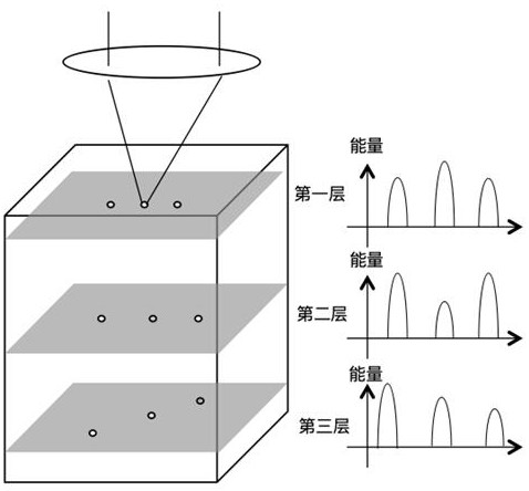
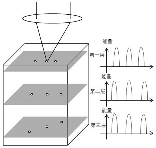
The invention relates to a three-dimensional multi-beam laser parameter regulation and control method and system; the method comprises the steps: carrying out the initialization of a laser system, obtaining a hologram of an output light field, generating a plurality of laser beams, and enabling the plurality of laser beams to enter a light spot energy and position sensing assembly through a lightpath, wherein the light spot energy and position sensing assembly sequentially collects energy and position information of all laser beams with focuses not located on the same plane; carrying out feedback modulation until the energy and position information are matched with preset target energy and position information, and controlling, by the laser system, the light paths to be switched so that the multiple laser beams can enter a target area through the light paths. In the invention, energy and position information of each laser beam is dynamically adjusted, parameter information and qualityof the output laser beams are monitored in real time and control is flexible; it is guaranteed that each laser beam entering a target area reaches a corresponding set target, optical system errors are effectively reduced, each laser beam can be modulated randomly and accurately; the method and system has effects of multiplying improvement of laser utilization rate.

Description

technical field [0001] The invention relates to the technical field of laser processing, in particular to a three-dimensional multi-beam laser parameter control method and system. Background technique [0002] Multi-beam control technology usually refers to the technology of controlling various parameters of multiple laser beams at the same time. Common controllable parameters include the number, direction, light intensity distribution (mode), light intensity, and optical power of the beams. When the beam converges the spherical wave front, the beam can be converged into a spot in three-dimensional space after passing through the positive lens, and the axial distance of the spot can be controlled by changing the position of the positive lens or the focal length of the lens. If combined with the beam pointing control technology , this light spot has three-dimensional space controllability. Three-dimensional multi-beams are widely used in medicine, optics, physics, microelect...

Claims


Application Information

Patent Timeline
Patent Type & Authority Patents(China)
IPC IPC(8): H01S3/00
CPCH01S3/0071
Inventor 翟中生刘顿张骆操文泽刘愿
Owner WUHAN JINDUN LASER TECH CO LTD
Learn More