
Oil separation equipment

An equipment and oil separation technology, applied in the field of oil pollution isolation equipment in waste water, can solve the problems of manual salvage of waste oil, low oil separation efficiency, agglomerated grease, etc., to improve environmental quality, fast oil separation, and prevent peculiar smell. the effect of leaking

Pending Publication Date: 2020-11-03
上海双解泵业制造有限公司
View PDF0 Cites 1 Cited by
  • Summary
  • Abstract
  • Description
  • Claims
  • Application Information

AI Technical Summary

Problems solved by technology

[0003] In order to overcome the above defects of the prior art, the present invention provides a kind of oil separation equipment, which solves the problems of low oil separation efficiency of traditional oil separation equipment, agglomerated grease in cold weather, easy blockage, and manual salvage of waste oil

Method used


Image

  • Oil separation equipment
  • Oil separation equipment

Examples


Embodiment Construction

[0018] The following will clearly and completely describe the technical solutions in the embodiments of the present invention with reference to the accompanying drawings in the embodiments of the present invention. Obviously, the described embodiments are only some, not all, embodiments of the present invention. Based on the embodiments of the present invention, all other embodiments obtained by persons of ordinary skill in the art without making creative efforts belong to the protection scope of the present invention.

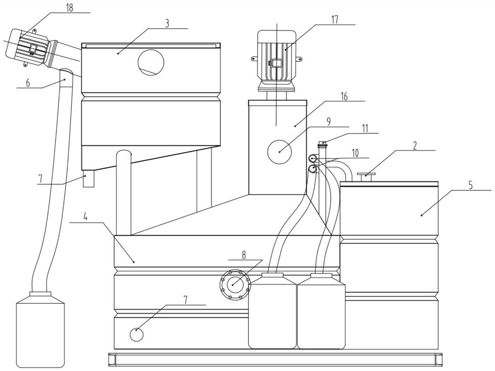
[0019] The working process of the present invention is as follows: connect the user's sewage oil and water main pipe from the equipment entrance to enter the slag-liquid separation box 3, and perform solid-liquid separation in the slag-liquid separation box 3, and the waste water can be divided into four diversion pipes to enter the oil-water separation box 4, waste water and grease After entering the oil-water separation box 4, the oil and water density differ...


PUM


Abstract

Oil separation equipment is disclosed. The equipment comprises a residue-liquid separation tank, an oil-water separation tank, an oil storage tank and a sewage lifting tank, wherein a liquid outlet ofthe residue-liquid separation tank is communicated with a liquid inlet of the oil-water separation tank, the bottom of the residue-liquid separation tank is arranged in an inverted cone shape, a sludge discharge port is formed in the cone bottom of the inverted cone, the upper portion of the oil-water separation tank is arranged in a right cone shape, the upper part of the right cone shape is communicated with the oil storage tank, an oil outlet of the oil storage tank is externally connected with a waste oil collecting barrel through a pipeline to discharge oil; a stirring device, a heatingdevice and a temperature control device are arranged in the oil storage tank; a water outlet of the oil-water separation tank is connected with a water inlet of the sewage lifting tank. The equipmentintegrates an automatic oil separation function, an electric heating constant-temperature function and an automatic sewage forced drainage function, is ingenious in design and excellent in configuration, and is special equipment for oil separation and forced drainage of underground restaurant wastewater. The whole process is automatic and integrally designed, oil separation, forced drainage and auxiliary heating are integrated, installation and operation are easy, the appearance is compact and attractive, and the basement installation space is reduced.

Description

technical field [0001] The invention relates to the field of equipment for isolating oil pollution in waste water, more specifically, it is an integrated oil-separating equipment with better oil-separating effect. Background technique [0002] The traditional oil separation equipment is the oil separation tank, and its working principle is to use the difference in the proportion of waste water and water to achieve the purpose of separation. The structure of the grease trap mostly adopts the advection type. The advection type means that the suspended matter is on the same plane. The water inlet and outlet of the grease trap are at both ends of the same plane, and flow through the pressure of the water inlet. The shape of the grease trap is generally rectangular. The oily wastewater enters the grease trap and flows slowly along the horizontal direction. During the flow, the oil product (with a lighter density than water) floats on the water surface and is pushed to the surface...

Claims


Application Information

Patent Timeline
Patent Type & Authority Applications(China)
IPC IPC(8): C02F1/40
CPCC02F1/40C02F2201/002
Inventor 胡龙文胡宝文张芳经徐新房
Owner 上海双解泵业制造有限公司
Learn More