Surface finish machining treatment system and treatment process after casting molding of casting part

A casting molding and processing system technology, used in manufacturing tools, metal processing equipment, grinding workpiece supports, etc., can solve the problems of inability to grind multiple wrenches, low grinding efficiency, and high labor intensity

Active Publication Date: 2020-10-27
江西晖旭实业有限公司
View PDF6 Cites 0 Cited by
  • Summary
  • Abstract
  • Description
  • Claims
  • Application Information

AI Technical Summary

Problems solved by technology

[0005] The present invention can solve the problems that most of the existing casting workpieces are manually ground by using a grinding machine, and the arc surface of the wrench cannot be evenly ground, and the castings will be worn out due to improper operation, and the manual work efficiency is low and the labor intensity is high. , can also solve the problem that the existing grinding equipment for casting workpieces cannot grind the irregular arc surface of the wrench well, and the polished surface cannot be cleaned in time, resulting in rust and residues on the polished surface still adhering to the arc surface of the wrench, affecting Grinding quality, it is impossible to polish multiple wrenches at the same time, and the problem of low grinding efficiency

Method used


Image

  • Surface finish machining treatment system and treatment process after casting molding of casting part
  • Surface finish machining treatment system and treatment process after casting molding of casting part
  • Surface finish machining treatment system and treatment process after casting molding of casting part

Examples


Embodiment Construction

[0027] The embodiments of the present invention will be described in detail below with reference to the accompanying drawings, but the present invention can be implemented in many different ways defined and covered by the claims.

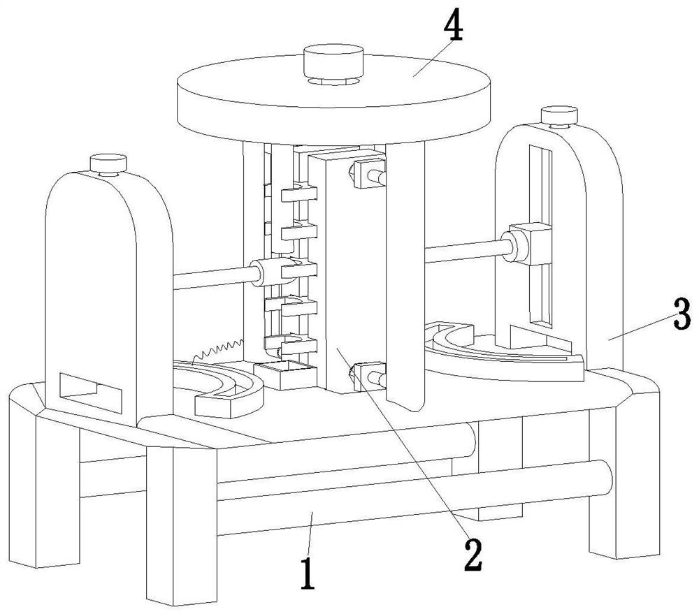
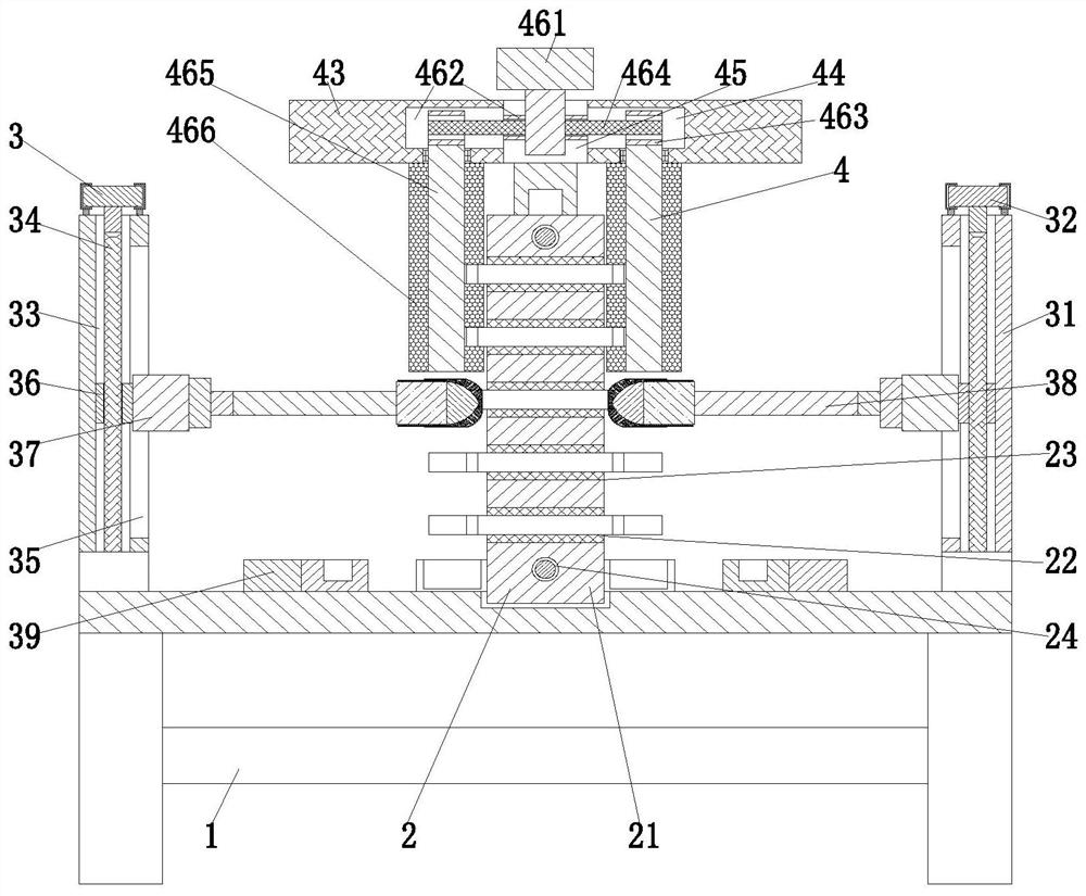
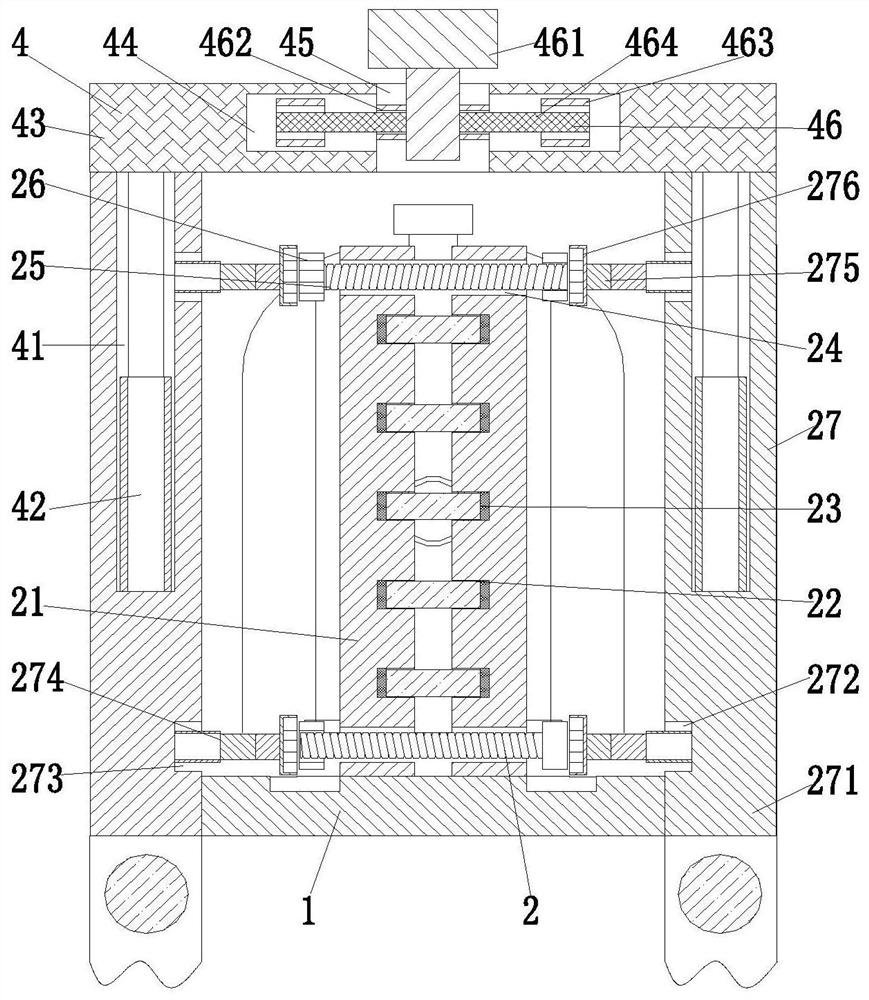
[0028] Such as Figure 1 to Figure 6 As shown, a casting surface finishing treatment system after pouring molding, including a support frame 1, a clamping device 2, a grinding device 3 and a cleaning device 4, the middle part of the support frame 1 is provided with a clamping device 2 and a cleaning device 4. The cleaning device 4 is located above the clamping device 2, and the grinding device 3 is symmetrically installed on the left and right ends of the support frame 1.

[0029] The middle part of the support frame 1 is equipped with a collection box 11 for collecting workpieces by sliding fit, and a filter screen is arranged in the collection box 11. During specific work, the left and right sides of the collection box 11 are provided with a colle...


PUM


Abstract

The invention relates to a surface finish machining treatment system and treatment process after casting molding of a casting part. The surface finish machining treatment system comprises a supportingframe, a clamping device, grinding devices and a cleaning device, the clamping device and the cleaning device are arranged in the middle of the supporting frame, the cleaning device is located abovethe clamping device, and the grinding devices are symmetrically installed at the left end and the right end of the supporting frame; the clamping device comprises a clamping plate, clamping grooves, rubber pads, threaded holes, a locking bolt, a nut cap and a locking mechanism, a groove is formed in the middle of the supporting frame, the clamping plate is installed in the groove in a sliding fitmode, the clamping grooves are evenly formed in the clamping plate, the rubber pads are arranged in the clamping grooves, and the threaded holes are vertically and symmetrically formed in the middle of the clamping plate. The problems that most of existing casting workpieces are polished manually through a polishing machine, the cambered surfaces of wrenches cannot be polished uniformly, castingsare abraded due to improper operation, the manual working efficiency is low, and the labor intensity is high can be solved.

Description

technical field [0001] The invention relates to the technical field of fine treatment of casting workpieces, in particular to a surface finishing treatment system and a treatment process of castings after pouring and molding. Background technique [0002] Casting workpiece refers to pouring liquid metal into a mold cavity that is suitable for the shape and size of the part, and waiting for it to cool and solidify to obtain a blank or part called a casting. Casting structure design: ensure its working performance and mechanical performance requirements, consider the requirements of casting process and alloy casting performance on casting structure, whether the casting structure design is reasonable or not, has a great impact on the quality, productivity and cost of castings. After the casting is poured and formed, there will be certain burrs or bumps on the surface of the casting. In order to ensure the overall aesthetics and quality of the casting, the burrs or bumps on the ...

Claims


Application Information

Patent Timeline
IPC IPC(8): B24B1/04B24B9/04B24B41/06B24B47/12B24B41/04B24B55/02B24B55/12B08B1/04
CPCB24B1/04B24B9/04B24B41/06B24B47/12B24B41/04B24B55/02B24B55/12B08B1/32B08B1/12
Inventor 丁建丽
Owner 江西晖旭实业有限公司
Why Eureka
Try Eureka