
Cold-formed thin-walled steel-concrete combined bridge deck continuous device and construction method

A technology of cold-formed thin-walled steel and combined bridge deck, which is applied to bridges, bridge parts, bridge materials, etc., and can solve problems such as poor construction, poor durability of unbonded materials, and impact on bridge durability and ride comfort

Pending Publication Date: 2020-10-20
JIANGNAN UNIV
View PDF0 Cites 0 Cited by
  • Summary
  • Abstract
  • Description
  • Claims
  • Application Information

AI Technical Summary

Problems solved by technology

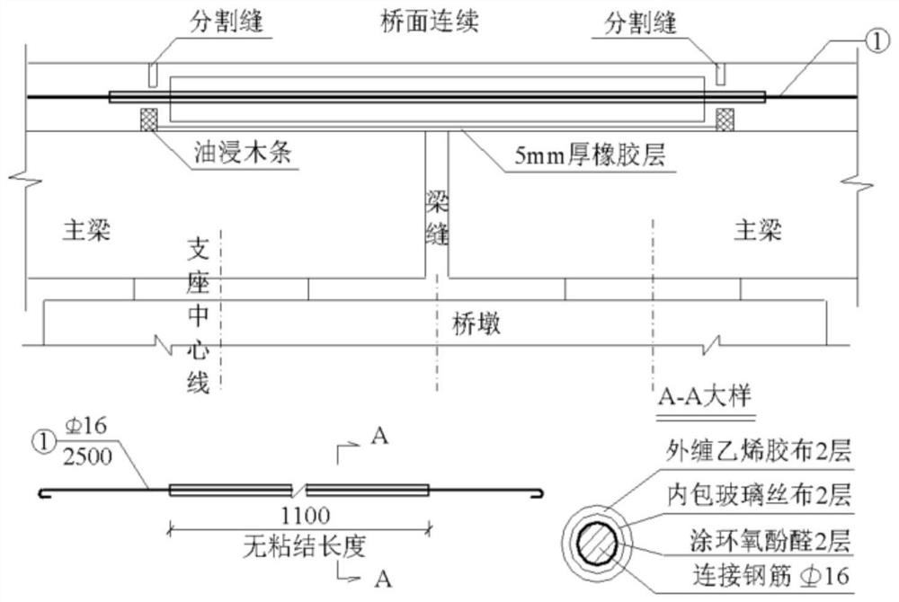
[0003] Since the 1970s, my country began to use the continuous bridge deck construction method, and it has been widely used on highways and municipal bridges, and the continuous bridge deck device is mainly based on tie rods (see figure 1 ), but due to problems such as poor construction and poor durability of unbonded materials, the continuous use effect of the tie-rod bridge deck is poor, and the tension transmitted to the continuous concrete of the bridge deck cannot be resisted by the continuous steel bars of the bridge deck and the bridge pavement steel mesh , Concrete cracking is prone to occur at the continuous part of the bridge deck, causing rainwater to infiltrate and erode the lower structure of the bridge, which seriously affects the durability and ride comfort of the bridge. In addition, the existing bridge deck continuous device has a complex structure and is inconvenient to assemble

Method used


Image

  • Cold-formed thin-walled steel-concrete combined bridge deck continuous device and construction method
  • Cold-formed thin-walled steel-concrete combined bridge deck continuous device and construction method
  • Cold-formed thin-walled steel-concrete combined bridge deck continuous device and construction method

Examples


Embodiment 1

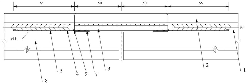
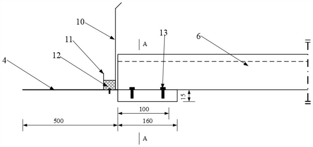
[0048] This embodiment provides a cold-formed thin-walled steel-concrete composite bridge deck continuous device applied to reinforced concrete simply supported girder bridges. Please refer to the attached Figure 2-4 .

[0049]The bridge deck continuous device is set on the reinforced concrete prefabricated T-beam 8, the upper layer of the prefabricated T-beam 8 is a 10cm thick C40 concrete pavement 1, and the top of the C40 concrete pavement 1 is a 10cm thick asphalt concrete pavement 2.

[0050] The bridge deck continuous device includes a steel standard section 3, the bottom of the steel plate standard section 3 is provided with an extended steel plate 4, and the extended steel plate 4 is connected with the concrete pavement layer 1, and the extended steel plate 4 is on the two sides of the steel plate standard section 3. End bottom transverse bridge direction welds a diameter 14mm, long 70cm longitudinal bridge direction connecting steel bar 5 every certain distance (for ...

Embodiment 2

[0061] This embodiment provides a continuous device and construction method for a cold-formed thin-walled steel-concrete composite bridge deck that can be quickly assembled without welding, including the following steps:

[0062] Step 1: Prefabricate steel standard sections and U-shaped drainage channels in the factory, including cutting C-shaped cold-formed thin-walled steel end limbs, specifically: C-shaped cold-formed thin-walled steel bottom plate at 200×50×15×3 Drill 4 bolt holes at each beam end, and at the same time drill four bolt holes at the corresponding positions on the support steel plate, then connect the C-shaped cold-formed thin-walled steel to the support steel plate with M14 hexagonal bolts, and connect the The steel standard section is assembled and spliced ​​with self-tapping and self-drilling screws along the direction of the transverse bridge to form the required width, and then a 20mm thick foam glue is bonded on the outside of the support steel plate, wh...

Embodiment 3

[0070] Such as Figure 8-12 As shown, the finite element simulation model of the cold-formed thin-walled steel-concrete composite bridge deck continuous device is established, and the distribution of steel plates and material properties are simulated strictly according to the design conditions. By applying mid-span loads to the main girder, the results show that, Under the action of different mid-span loads, the maximum longitudinal stress of the surface concrete of the device of the present invention is about 1.5 MPa, indicating that the composite structure of the present invention has good vertical rigidity.


PUM


Abstract

The invention discloses a cold-formed thin-walled steel-concrete combined bridge floor continuous device applied to a reinforced concrete simply supported beam bridge. The cold-formed thin-walled steel-concrete combined bridge floor continuous device comprises a prefabricated steel standard section that is formed by connecting C-shaped cold-formed thin-walled section steel and a steel plate through self-tapping and self-drilling screws; the steel standard section is supported on a cement mortar leveling layer and an asphalt felt on the surface of a beam plate, self-tapping and self-drilling screws are arranged on the two sides of the steel standard section and connected with a stainless steel U-shaped drainage groove, a waterproof sealant is arranged in the U-shaped drainage groove in an embedded mode, and a steel plate on one side extends to a bridge floor. Concrete cracking can be effectively prevented, seeping water is drained to the two sides of a bridge, concrete erosion is prevented, assembling and splicing are convenient on a construction site, welding is not needed, the construction speed is high, and the cost is low.

Description

technical field [0001] The invention relates to the field of continuous bridge decks, in particular to a bridge deck continuous device and a bridge deck continuous method of simply supported girder bridges. Background technique [0002] Bridges are buildings built by humans to overcome natural obstacles in their life and production activities. Most bridges need to set expansion joints between the beam ends of two adjacent spans, between the beam ends and the abutment, at both ends of the hanging beams, and at the hinges of the bridge, so as to adapt to the expansion of the beam structure under the action of temperature stress. The rotational and longitudinal displacements of the beam ends are caused by shrinkage deformation and vehicle loads. For multi-span simply supported hollow slab girder bridges, in order to reduce the number of bridge deck expansion joints, improve the ride comfort and the service life of the bridge, the design method of "continuous bridge deck" is of...

Claims


Application Information

Patent Timeline
Patent Type & Authority Applications(China)
IPC IPC(8): E01D19/12E01D21/00E01D19/08E01D101/30E01D101/26
CPCE01D19/086E01D19/125E01D21/00E01D2101/26E01D2101/30
Inventor 王城泉王丽孙泽轩邹昀刘悦李天祺
Owner JIANGNAN UNIV
Learn More