
Reinforced concrete block, wall formed by masonry and masonry method

A reinforced, block technology, applied in the direction of walls, buildings, building materials, etc., can solve the problems of inability to take into account thermal insulation performance and strength performance, thermal insulation holes cannot be covered, and the masonry process is troublesome. High toughness and high accuracy

Active Publication Date: 2020-10-16
东阳市智林科技有限公司
View PDF8 Cites 0 Cited by
  • Summary
  • Abstract
  • Description
  • Claims
  • Application Information

AI Technical Summary

Problems solved by technology

[0003] 1. During the masonry process, it is necessary to install the reinforcement cage first, and then insert the blocks from the top of the reinforcement cage, or build the blocks first, and then install the reinforcement cage from the top of the blocks. The process is very troublesome;
[0004] 2. Only one of thermal insulation mortar or concrete mortar can be poured in the thermal insulation hole, which cannot take into account both thermal insulation performance and strength performance;
[0005] 3. The thermal insulation holes cannot cover the joints of the side panels of horizontally adjacent blocks, so there will be thermal bridges at the joints, which will affect the overall thermal insulation effect

Method used


Image

  • Reinforced concrete block, wall formed by masonry and masonry method
  • Reinforced concrete block, wall formed by masonry and masonry method
  • Reinforced concrete block, wall formed by masonry and masonry method

Examples


Embodiment Construction

[0049] The following are specific embodiments of the present invention and in conjunction with the accompanying drawings, the technical solutions of the present invention are further described, but the present invention is not limited to these embodiments.

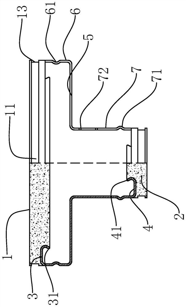
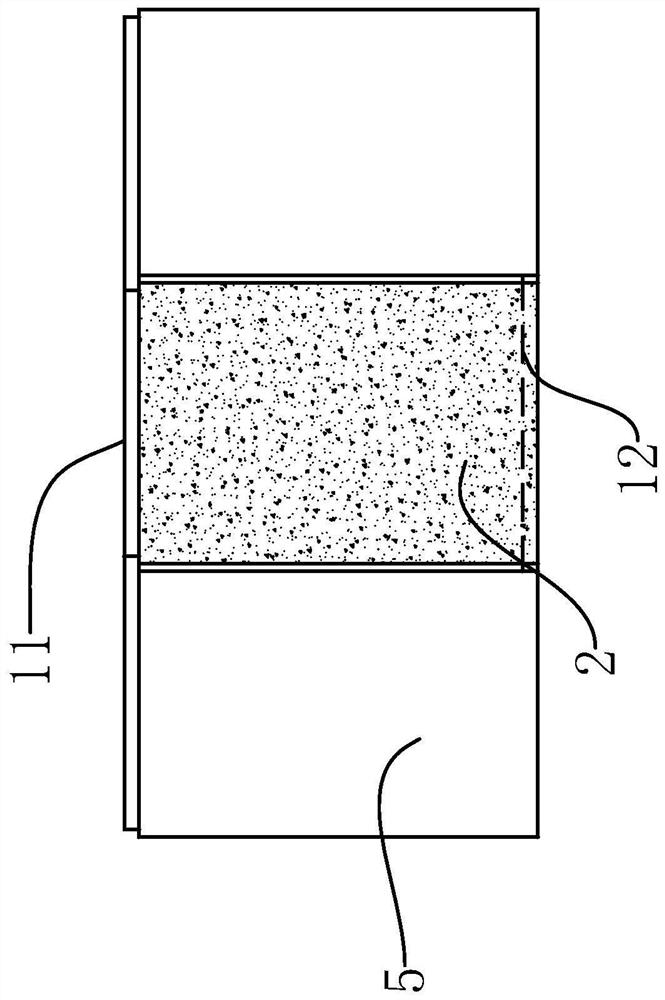
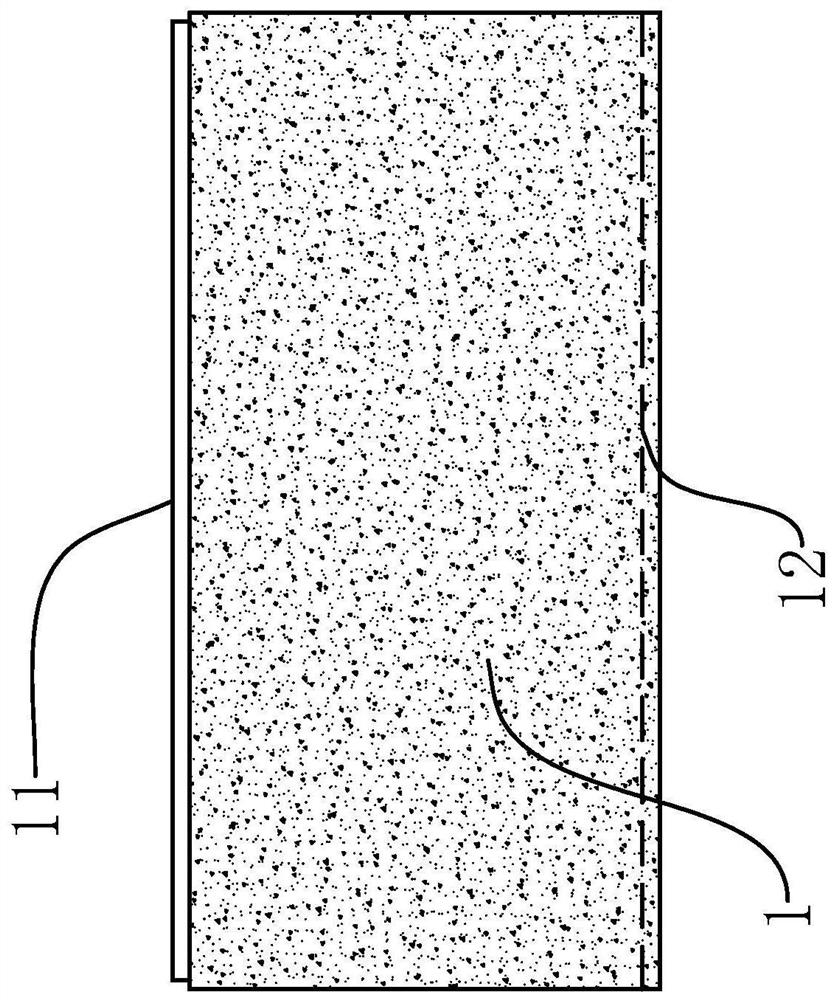
[0050] Such as Figure 1-6 As shown, a reinforced block of the present invention includes a main wall panel 1 and an auxiliary wall panel 2 made of concrete material and a rectangular plate structure, the outer side of the main wall panel 1 and the outer side of the auxiliary wall panel 2 are parallel to each other, A skeleton of steel structure is provided between the main wall panel 1 and the auxiliary wall panel 2. The skeleton is a hollow frame structure with a T-shaped cross section, and the vertical height of the skeleton perpendicular to the cross section of the skeleton, the vertical height of the main wall panel 1 and The auxiliary wall plates 2 have the same vertical height, and the skeleton includes the main fix...


PUM


Abstract

The invention provides a reinforced concrete block, a wall formed by masonry and a masonry method, and belongs to the field of concrete blocks. The problem of the troublesome existing concrete block masonry process is solved. The reinforced concrete block comprises a main wall plate and a secondary wall plate, a steel structure skeleton is arranged between the main wall plate and the secondary wall plate, and the skeleton is of a T-shaped hollow frame structure. The skeleton includes a main fixed plate, a secondary fixed plate, two baffles, two main connecting plates and two secondary connecting plates, and the two baffles are the same spacing with the main fixed plate and are less than the distance between the two baffles and the secondary fixed plate. Vertical positioning grooves and vertical positioning bars are separately arranged on the outer side surfaces of the main connecting plates and the outer side surfaces of the secondary connecting plates, horizontal positioning bars areseparately arranged on the top surface of the main wall plate and the top surface of the secondary wall plate, horizontal positioning grooves are separately formed in the bottom surface of the main wall plate and the bottom surface of the secondary wall plate, and reinforcement grooves formed in a transverse grooving direction are further formed in the upper sides of the secondary connecting plates. The concrete block has the advantages of both concrete materials and steel structure materials, the strength is higher and the toughness is greater, and the embrittlement of the concrete block in the process of handling or masonry is avoided.

Description

technical field [0001] The invention belongs to the technical field of blocks, and relates to a reinforced block, a wall formed by masonry and a masonry method. Background technique [0002] The main body of the hollow prefabricated block is generally made of concrete, and the internal hollow area is used to penetrate the steel cage to improve the strength of the wall formed by the masonry; the application number is 201910834694.1, and the name is "a block and its production mold and production method and The Chinese invention patent of "wall formed by masonry", which includes a concrete body, the body includes two wall panels, ribs and two side panels, and the ribs and two side panels are separated between the two wall panels to form two Insulation holes, during the masonry process, a steel cage is installed inside the insulation block to form a high-strength wall structure. But it has the following problems: [0003] 1. During the masonry process, it is necessary to inst...

Claims


Application Information

Patent Timeline
Patent Type & Authority Applications(China)
IPC IPC(8): E04C1/41E04B2/46E04B2/54E04B1/78
CPCE04C1/41E04B2/46E04B2/54E04B1/78E04B2002/0202
Inventor 张丽丽
Owner 东阳市智林科技有限公司
Learn More