


Quick Research
Generate reliable direction feasibility study reports for your R&D in just a few steps.

Technical Q&A
Discover and master advanced knowledge NOW. Basics, ideas, possibilities, all at once.

Find Solutions
As an expert in R&D theories, this can generate solutions to your technical problems instantly.

Evaluate Feasibility
Analyze your overall solution with one click, know your potential R&D risks in advance.

Monitor Landscape
Get weekly tech updates, stay abreast of the latest tech innovations and key insights.
Passive micro-mixer for chemiluminescence detection and use method of passive micro-mixer
A chemiluminescence detection and micro-mixer technology is applied in the fields of microfluidic technology and biochemical detection, which can solve the problems such as the inability to achieve the strongest luminescence intensity, the complex structure of the microfluidic chip, and the increase of the length of the detection channel, so as to speed up the chemical reaction. speed, shorten the mixing distance, and improve the effect of detection sensitivity
- Summary
- Abstract
- Description
- Claims
- Application Information
AI Technical Summary
Problems solved by technology
Method used
Image


Examples
Embodiment 1
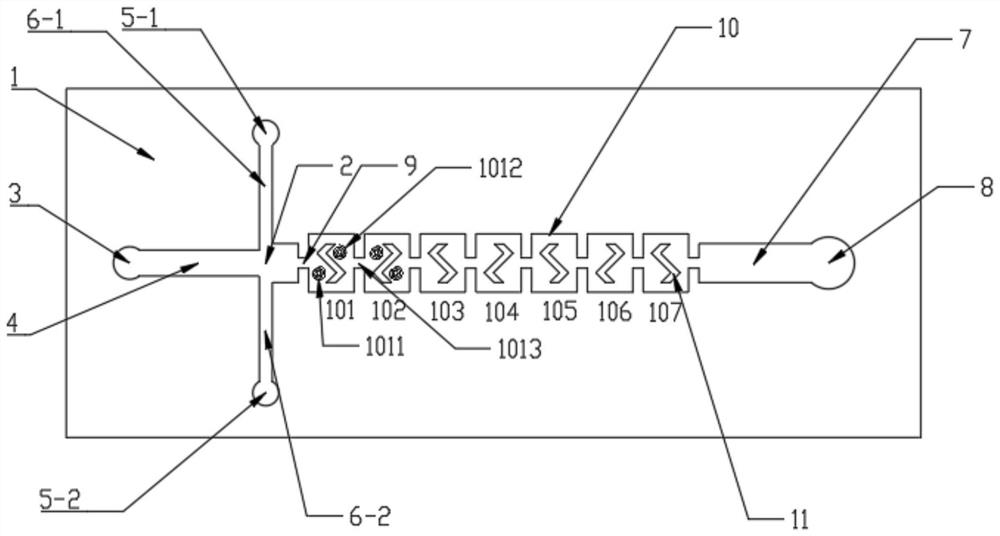
[0040] A cross-type passive micromixer for chemiluminescent detection, such as figure 1 As shown, it includes a micro-mixer matrix 1 and a cross-shaped channel arranged inside it. The four directions of the cross-shaped channel are: the sample channel 4 to be tested, the first sheath flow channel 6-1, the detection channel 10 and the second channel. The outflow end of the sheath flow channel 6-2, the sample channel 4 to be tested, the first sheath flow channel 6-1, and the second sheath flow channel 6-2 are connected to the inflow end of the detection channel 10 through the mixing chamber 2, and the mixing chamber 2 is connected to the detection channel 10 through a narrow connection channel 9, the outflow end of the detection channel 10 is connected to the waste liquid pool 8 through the waste liquid outflow channel 7, and the inflow end of the sample channel 4 to be tested is connected to the sample liquid storage pool to be tested 3, the inflow ends of the first sheath flow...
Embodiment 2
[0047] A Y-type passive micro-mixer for chemiluminescence detection, comprising a micro-mixer base 1 and a Y-shaped channel arranged inside it, such as Figure 5 As shown, the three directions of the Y-shaped channel are: the sample channel 4 to be tested, the sheath flow channel 6, the detection channel 10, the sample channel 4 to be tested, the outflow end of the sheath flow channel 6 and the inflow end of the detection channel 10 Connected through the mixing chamber 2, the mixing chamber 2 and the detection channel 10 are connected through a narrow connection channel 9, the outflow end of the detection channel 10 is connected to the waste liquid pool 8 through the waste liquid outflow channel 7, and the inflow of the sample channel 4 to be tested The end is connected with the sample storage tank 3 to be tested, and the inflow end of the sheath flow channel 6 is connected with the sheath flow storage tank 5 .
[0048] The detection channel 10 is composed of more than three m...
Embodiment 3
[0053] A method for using the cross-type passive micro-mixer of embodiment 1, adopting the cross-type passive micro-mixer of embodiment 1 to carry out chemiluminescence detection transition metal cobalt ion concentration, comprising the steps:
[0054] (1) To clean the flow path, use 1.0mol L sequentially -1 Wash with NaOH for 30 minutes, then wash with ultrapure water for 5 minutes;
[0055] (2) The sample storage tank 3 to be tested, the first sheath flow storage tank 5-1, and the second sheath flow storage tank 5-2 are respectively used to hold the cobalt chloride solution to be tested, the hydrogen peroxide solution and the Minol solution;
[0056] Negative pressure is applied to the waste liquid tank 8, or positive pressure is applied to the sample storage tank 3 to be tested, the first sheath flow storage tank 5-1, and the second sheath flow storage tank 5-2 to drive the cobalt chloride solution , hydrogen peroxide solution and luminol solution move to the detection ch...
PUM
| Property | Measurement | Unit |
|---|---|---|
| Width | aaaaa | aaaaa |
Abstract
Description
Claims
Application Information
 - R&D Engineer
- R&D Manager
- IP Professional
- Industry Leading Data Capabilities
- Powerful AI technology
- Patent DNA Extraction
Browse by: Latest US Patents, China's latest patents, Technical Efficacy Thesaurus, Application Domain, Technology Topic, Popular Technical Reports.
© 2024 PatSnap. All rights reserved.Legal|Privacy policy|Modern Slavery Act Transparency Statement|Sitemap|About US| Contact US: help@patsnap.com