Computer numerical control polishing device for precision machining of sapphire

A technology of precision machining and polishing device, applied in the direction of grinding drive device, metal processing equipment, grinding/polishing equipment, etc., can solve the problems of increasing the labor intensity of workers, affecting the quality of polishing, arm fatigue, etc. Quality, convenient operation and use, the effect of reducing labor intensity

Inactive Publication Date: 2020-09-29
深圳市蓝宝源光电科技有限公司
View PDF6 Cites 1 Cited by
  • Summary
  • Abstract
  • Description
  • Claims
  • Application Information

AI Technical Summary

Problems solved by technology

[0002] Sapphire is a general name for corundum gemstones of other colors except red ruby. After cutting, sapphire needs to be polished on the inner surface. During the polishing process, the sapphire needs to be placed on the table or by a staff member. Hold it and then polish it through the polishing disc, but holding it by hand will cause the fatigue of the arm and increase the labor intensity of the staff. If it is placed and polished on the table, the sapphire needs to be clamped, but the existing clamping and fixing If the device is not good, the sapphire will move during the polishing process, which will affect the quality of polishing. Therefore, it is necessary to provide a CNC polishing device for sapphire precision machining to solve the above problems

Method used


Image

  • Computer numerical control polishing device for precision machining of sapphire
  • Computer numerical control polishing device for precision machining of sapphire

Examples


Embodiment 1

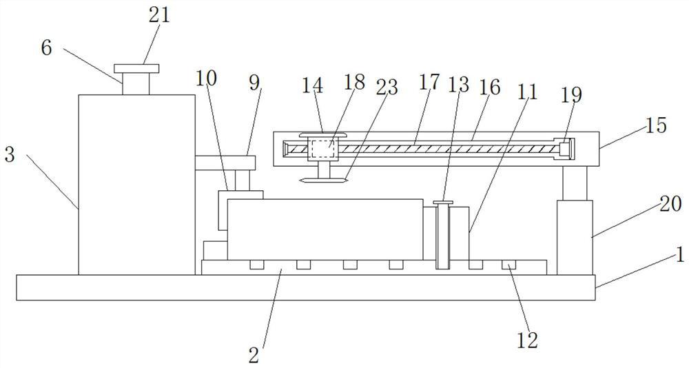
[0023] see Figure 1-2 According to an embodiment of the present invention, a numerically controlled polishing device for sapphire precision machining includes a bottom plate 1, one side of the bottom plate 1 is provided with a placement platform 2, and one side of the placement platform 2 is provided with a limiting device, and the placement A clamping device is provided on the side of the table 2 away from the limiting device, and the clamping device includes a frame body 3, and a first motor 4 is provided inside the frame body 3, and the extension of the first motor 4 The end is provided with a first threaded rod 5, and one end of the first threaded rod 5 away from the first motor 4 is threaded with a threaded barrel 6, and one end of the threaded barrel 6 is fixedly provided with an L-shaped plate 7, the L The end of the template 7 away from the threaded cylinder 6 is penetrated with a slide rod 8, both ends of the slide rod 8 are fixedly connected to the inner wall of the...

Embodiment 2

[0025] see Figure 1-2 , for the supporting sliding device, the supporting sliding device includes a horizontal plate 15, one side of the horizontal plate 15 is provided with a chute 16, the inside of the chute 16 is provided with a second threaded rod 17, and the first Two threaded rods 17 are threaded with a slide block 18, one side of the slide block 18 is fixedly connected with the second motor 14, and one end of the second threaded rod 17 is connected with the output end of the third motor 19 to support the sliding device It can realize that the polishing disk 23 can realize the process of polishing the polishing disk when the sapphire on the placement table 2 is polished; for the chute 16, one end of the chute 16 is located on the horizontal plate 15 There is a placement slot, the third motor 19 is located inside the placement slot, and one end of the horizontal plate 15 is provided with a placement slot, which can realize the process of placing the third motor 19, avoid...

Embodiment 3

[0027] Embodiment one:

[0028] see Figure 1-2 According to an embodiment of the present invention, a numerically controlled polishing device for sapphire precision machining includes a bottom plate 1, one side of the bottom plate 1 is provided with a placement platform 2, and one side of the placement platform 2 is provided with a limiting device, and the placement A clamping device is provided on the side of the table 2 away from the limiting device, and the clamping device includes a frame body 3, and a first motor 4 is provided inside the frame body 3, and the extension of the first motor 4 The end is provided with a first threaded rod 5, and one end of the first threaded rod 5 away from the first motor 4 is threaded with a threaded barrel 6, and one end of the threaded barrel 6 is fixedly provided with an L-shaped plate 7, the L The end of the template 7 away from the threaded cylinder 6 is penetrated with a slide rod 8, both ends of the slide rod 8 are fixedly connecte...


PUM


Abstract

The invention discloses a computer numerical control polishing device for precision machining of a sapphire. The computer numerical control polishing device comprises a baseplate, and a placing tableis arranged on one side of the baseplate; a limiting device is arranged on one side of the placing table, and a clamping device is arranged on the side, far away from the limiting device, of the placing table; the clamping device comprises a frame body, and a first motor is arranged in the frame body; a first threaded rod is arranged at the protruding end of the first motor, and a thread barrel isarranged at the end, far away from the first motor, of the first threaded rod; one end of the thread barrel is fixedly provided with an L-type plate in a threaded mode, and the end, far away from thethread barrel, of the L-type plate is provided with a sliding rod in a penetrating mode; and the two ends of the sliding rod are each connected with the inner wall of the frame body fixedly. The computer numerical control polishing device has the beneficial effects of the simple structure and convenient operation and use, and the placing stability of the sapphire during polishing is improved, sothat the polishing quality is improved; and the sapphire damage is reduced, and the machining safety is improved greatly.

Description

technical field [0001] The invention relates to the field of sapphire processing and design, in particular to a numerically controlled polishing device for sapphire precision processing. Background technique [0002] Sapphire is a general name for corundum gemstones of other colors except red ruby. After cutting, sapphire needs to be polished on the inner surface. During the polishing process, the sapphire needs to be placed on the table or by a staff member. Hold it and then polish it through the polishing disc, but holding it by hand will cause the fatigue of the arm and increase the labor intensity of the staff. If it is placed and polished on the table, the sapphire needs to be clamped, but the existing clamping and fixing If the device is not good, the sapphire will move during the polishing process, which will affect the quality of polishing. Therefore, it is necessary to provide a numerically controlled polishing device for sapphire precision machining to solve the ab...

Claims


Application Information

Patent Timeline
IPC IPC(8): B24B29/02B24B41/06B24B41/02B24B47/12B24B47/22
CPCB24B29/02B24B41/02B24B41/06B24B47/12B24B47/22
Inventor 李浩瀚
Owner 深圳市蓝宝源光电科技有限公司
Why Eureka
Try Eureka