
Novel ultra-wideband multi-channel receiving system

A multi-channel receiving, ultra-broadband technology, applied in transmission systems, electrical components, etc., can solve the problems of unreasonable product circuit structure design distribution, impact of batch product performance consistency, poor image and spurious suppression performance, etc. Amplitude and phase consistency between multiple channels, good amplitude and phase consistency between multiple channels, and the effect of achieving in-band gain flatness

Pending Publication Date: 2020-09-25
WUXI HUACE ELECTRONICS SYST
View PDF0 Cites 7 Cited by
  • Summary
  • Abstract
  • Description
  • Claims
  • Application Information

AI Technical Summary

Problems solved by technology

[0003] Limited by the manufacturing level and device performance indicators, the frequency scheme and integrated design technology of the receiving system often have defects in achieving broadband and high performance, such as poor image and spurious suppression performance due to unreasonable frequency band division. The performance requirements of spurious suppression add a large number of additional filters to meet the miniaturization design requirements, the unreasonable distribution of product circuit structure design introduces spurious and phase noise deterioration, and the limitation of manufacturing level limits the performance consistency of batch products. Influences, etc., ultimately lead to high manufacturing costs and difficult industrialization of ultra-wideband multi-channel receiving systems

Method used


Image

  • Novel ultra-wideband multi-channel receiving system
  • Novel ultra-wideband multi-channel receiving system
  • Novel ultra-wideband multi-channel receiving system

Examples


Embodiment Construction

[0031] The specific embodiments of the present invention will be further described below in conjunction with the accompanying drawings.

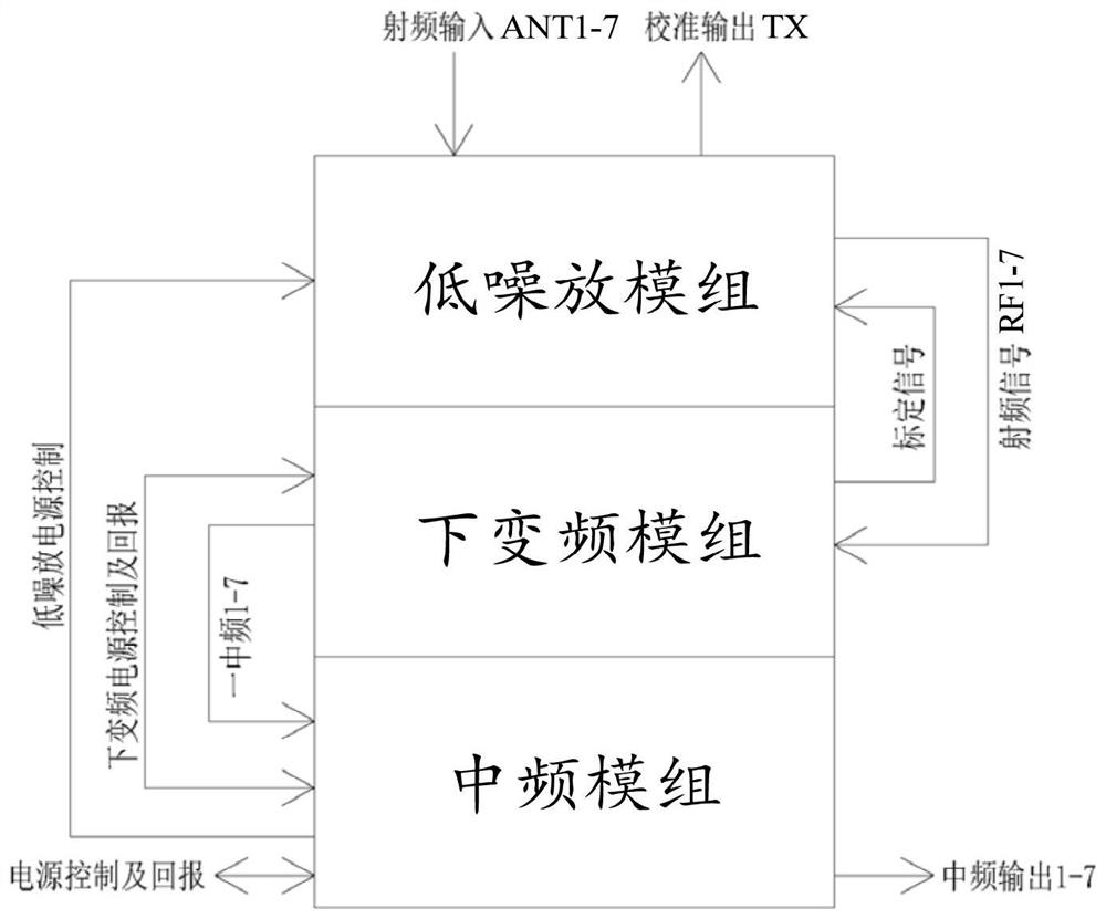
[0032] This application discloses a new ultra-wideband multi-channel receiving system, its principle block diagram is as follows figure 1 As shown, the system includes a power supply module, a low-noise amplifier module, a down-conversion module, and an intermediate frequency module connected in sequence. The modules are interconnected using flexible RF cables and rectangular connectors. module, down-conversion module and intermediate frequency module.

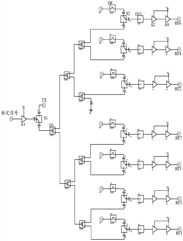
[0033] The low-noise amplifier module is connected to the antenna to implement low-noise amplification of N-channel received signals and output N-channel radio frequency signals. In this application, N=7. Its circuit diagram is as figure 2 As shown, the low noise amplifier module includes a limiter D8, a first radio frequency switch S2, a first attenuator D15 and a first amplifier, and th...


PUM


Abstract

The invention discloses a novel ultra-wideband multi-channel receiving system, and relates to the technical field of microwave communication. The system comprises a low-noise amplifier module, a down-conversion module and an intermediate frequency module which are connected in sequence; the low-noise amplifier module is connected with an antenna and outputs N-channel radio frequency signals; the down-conversion module comprises a switch filtering module and a first local oscillator power division network module; in each channel of the down-conversion module, the switch filtering module dividesthe radio-frequency signal into a predetermined low-frequency radio-frequency signal and a predetermined high-frequency radio-frequency signal, the predetermined low-frequency radio-frequency signalis directly transmitted to the intermediate-frequency module, and the predetermined high-frequency radio-frequency signal is transmitted to the intermediate-frequency module after being subjected to primary frequency mixing with the first local oscillation signal; the intermediate frequency module comprises a second local oscillator power division network module; the predetermined low-frequency radio-frequency signal and the primary frequency mixing radio-frequency signal are respectively and correspondingly accessed to each channel of the intermediate-frequency module and are subjected to secondary frequency mixing with the second local oscillation signal to output an intermediate-frequency signal, and mirror image interference and stray of the broadband receiving front end can be effectively suppressed through reasonable segmentation processing of the whole frequency band.

Description

technical field [0001] The invention relates to the technical field of microwave communication, in particular to a novel ultra-wideband multi-channel receiving system. Background technique [0002] In recent years, with the development of microwave devices and processes, the design of microwave circuits has become increasingly mature. Coupled with the many advantages of microwave technology, countries around the world have widely used microwave technology in systems such as radar, communication, navigation, telemetry, and electronic warfare. With the development of satellite communication, electronic countermeasures, radar and other technologies, especially due to the increasing shortage of radio communication frequency resources, the frequency intervals allocated to various communication systems are getting closer, the application frequencies are getting higher and higher, and the frequency bands are getting wider and wider. Width, will inevitably put forward higher and hig...

Claims


Application Information

Patent Timeline
Patent Type & Authority Applications(China)
IPC IPC(8): H04B1/10H04B1/08
CPCH04B1/10H04B1/08
Inventor 李成锋
Owner WUXI HUACE ELECTRONICS SYST
Learn More