
Method for reducing array element scale of spherical cylindrical array in sparse manner

A sparse, surface array technology, applied to antenna arrays, individually powered antenna arrays, and energy reduction, etc., can solve the problem that the optimization results are prone to fall into local optimal solutions, the gain and sidelobe characteristics are deteriorated, and the gain of the sparse array is full. Array low and other problems, to achieve excellent sparse effect, improve design efficiency, and be beneficial to engineering implementation.

Active Publication Date: 2020-09-18
10TH RES INST OF CETC
View PDF7 Cites 4 Cited by
  • Summary
  • Abstract
  • Description
  • Claims
  • Application Information

AI Technical Summary

Problems solved by technology

[0004] The main lobe width of the beam of the sparse array antenna is almost the same as the main lobe width of the full array with the same caliber, so that under the premise that the antenna cost is roughly the same, the sparse array antenna has more advantages than the full array antenna with the same number of array elements. Larger apertures, and thus narrower mainlobe widths, provide better resolution of targets, however gain and sidelobe characteristics necessarily deteriorate as the array is thinned out
In addition, for the surface thinning process, if the entire spherical surface is directly used for the thinning algorithm, it will not only increase the space-time complexity of the algorithm, but also the optimization result will easily fall into the local optimal solution, which is not conducive to engineering implementation. There will also be disadvantages such as lower gain than the full array with the same aperture
Therefore, there is currently no perfect and mature sparse conformal spherical-cylindrical array that can meet the needs of engineering realization.

Method used


Image

  • Method for reducing array element scale of spherical cylindrical array in sparse manner
  • Method for reducing array element scale of spherical cylindrical array in sparse manner
  • Method for reducing array element scale of spherical cylindrical array in sparse manner

Examples


Embodiment Construction

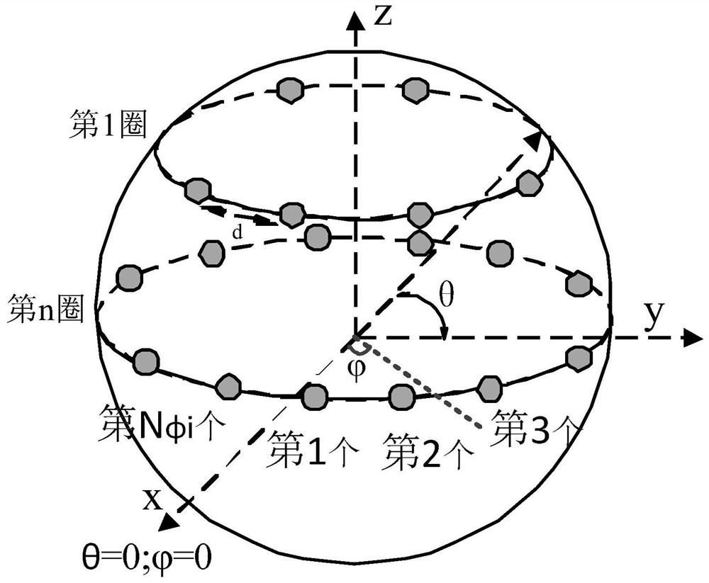
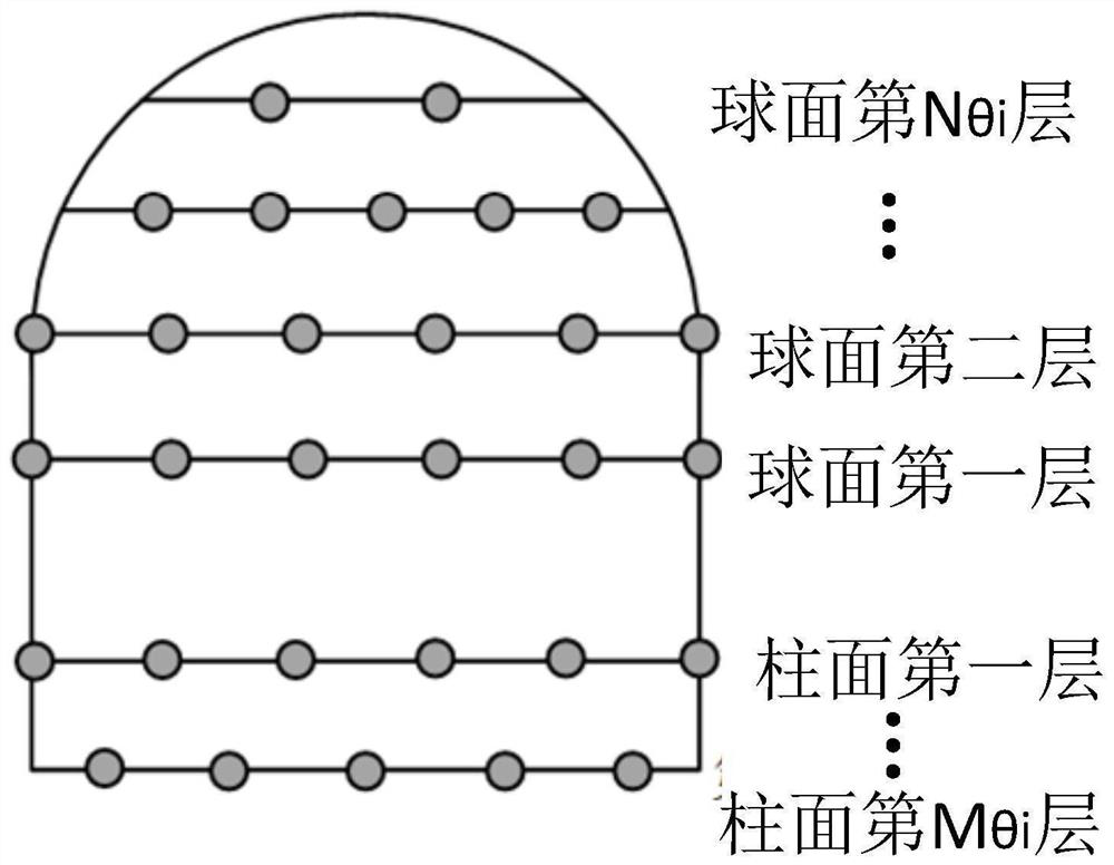
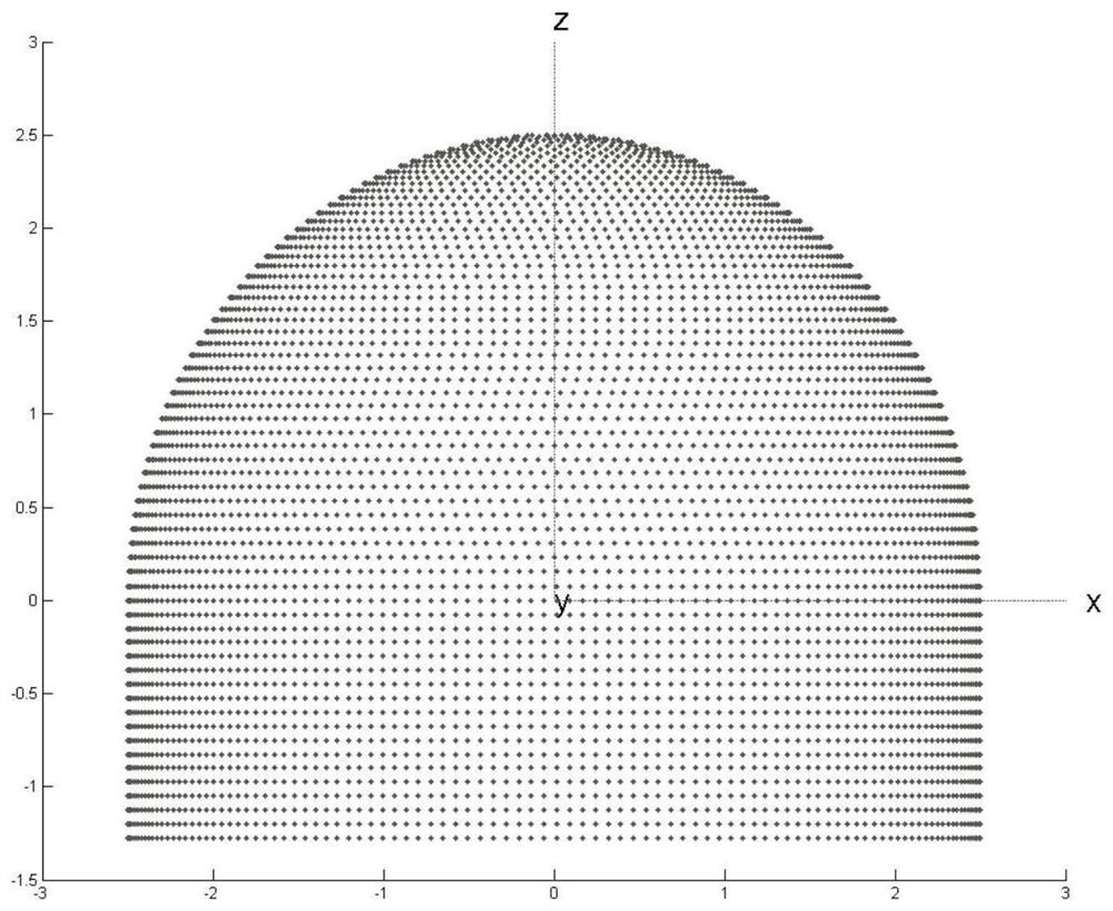
[0030] refer to Figure 1-Figure 9 . According to the present invention, adopt processing step as follows:

[0031] Step 1: If figure 1 As shown in , establish a full-array model of spherical cylinders with half-wavelength equal spacing and uniform arrangement

[0032] The array coordinate system is defined according to the rule of uniform arrangement of half-wavelength antenna elements in the antenna sub-array, and the antenna elements are arranged according to the center of the equal-area area of ​​the spherical-cylindrical array to construct a spherical-cylindrical full-scale array with half-wavelength equal intervals and uniform arrangement. array model.

[0033] Step 2: Establish a sparse sphero-cylindrical array model based on surface sub-arrays. Based on the full-array model of sphero-cylindrical arrays that are evenly spaced at half-wavelengths as described in step 1, the surface sub-array is used as the basic unit to divide the entire sphere into Form several surf...


PUM


Abstract

The invention discloses a method for reducing the array element scale of a spherical surface array in a sparse manner, and aims to provide a method capable of reducing the array scale after sparsification and maintaining electrical performance equivalent to that of a full array at the same time. The method is realized through the following technical scheme: the method comprises the following steps: defining an array coordinate system according to a rule of half-wavelength uniform arrangement of antenna units in the antenna subarray; adopting a sparse optimization algorithm to set initial parameters, construct a constraint matrix, generate an initial group, sparsify the sub-array, and calculating a fitness function of each curved surface sub-array individual in the group to form a sparsified basic sub-array unit with optimal fitness; constructing a spherical cylindrical surface array model based on curved surface subarray level sparseness by the sparsified basic subarray units accordingto a spherical cylindrical surface array equal-area region center arrangement rule; and finally, increasing the diameter of the spherical surface to obtain a spliced sparse spherical cylindrical surface antenna array, and compensating the total synthetic gain of the antenna array by increasing the unit gain to obtain a gain value and a minor lobe which are equivalent to those of a spherical cylindrical surface full array.

Description

technical field [0001] The invention belongs to the technical field of antennas, and in particular relates to a method for reducing the scale of a sphero-cylindrical array element through thinning. Background technique [0002] At present, by exciting high-frequency currents with different amplitudes and phases to different antenna elements in the array antenna, a phased array antenna that can scan the space in the maximum radiation direction of electromagnetic waves can be realized. However, because the planar phased array cannot achieve the beam coverage of the entire airspace and cannot meet the needs of the entire airspace measurement and control communication function, the spherical phased array antenna came into being. One of the most significant advantages of the spherical phased array antenna is that the beam coverage of the entire airspace can be achieved by activating different areas of the spherical cylindrical array. However, the spherical conformal array is aff...

Claims


Application Information

Patent Timeline
Patent Type & Authority Applications(China)
IPC IPC(8): G06F30/20H01Q21/06
CPCG06F30/20H01Q21/061Y02E60/00
Inventor 杨龙刘田张志亚周文涛谢伟
Owner 10TH RES INST OF CETC
Learn More