Polycrystalline silicon ingot furnace

A polysilicon ingot casting furnace and furnace body technology, which is applied in the directions of polycrystalline material growth, single crystal growth, single crystal growth, etc., can solve the problem that the fixed heat insulation block is difficult to meet, and achieve heat preservation, avoid overheating and melting, and reduce heat loss effect

Pending Publication Date: 2020-09-15
CENT SOUTH UNIV
View PDF0 Cites 0 Cited by
  • Summary
  • Abstract
  • Description
  • Claims
  • Application Information

AI Technical Summary

Problems solved by technology

Ingot casting furnaces equipped with fixed position insulation blocks will be subject to technological limitations, so fixed insulation blocks are difficult to meet the needs of existing ingot casting processes

Method used


Image

  • Polycrystalline silicon ingot furnace
  • Polycrystalline silicon ingot furnace
  • Polycrystalline silicon ingot furnace

Examples


Embodiment approach

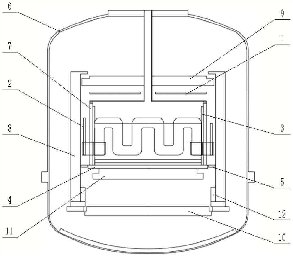
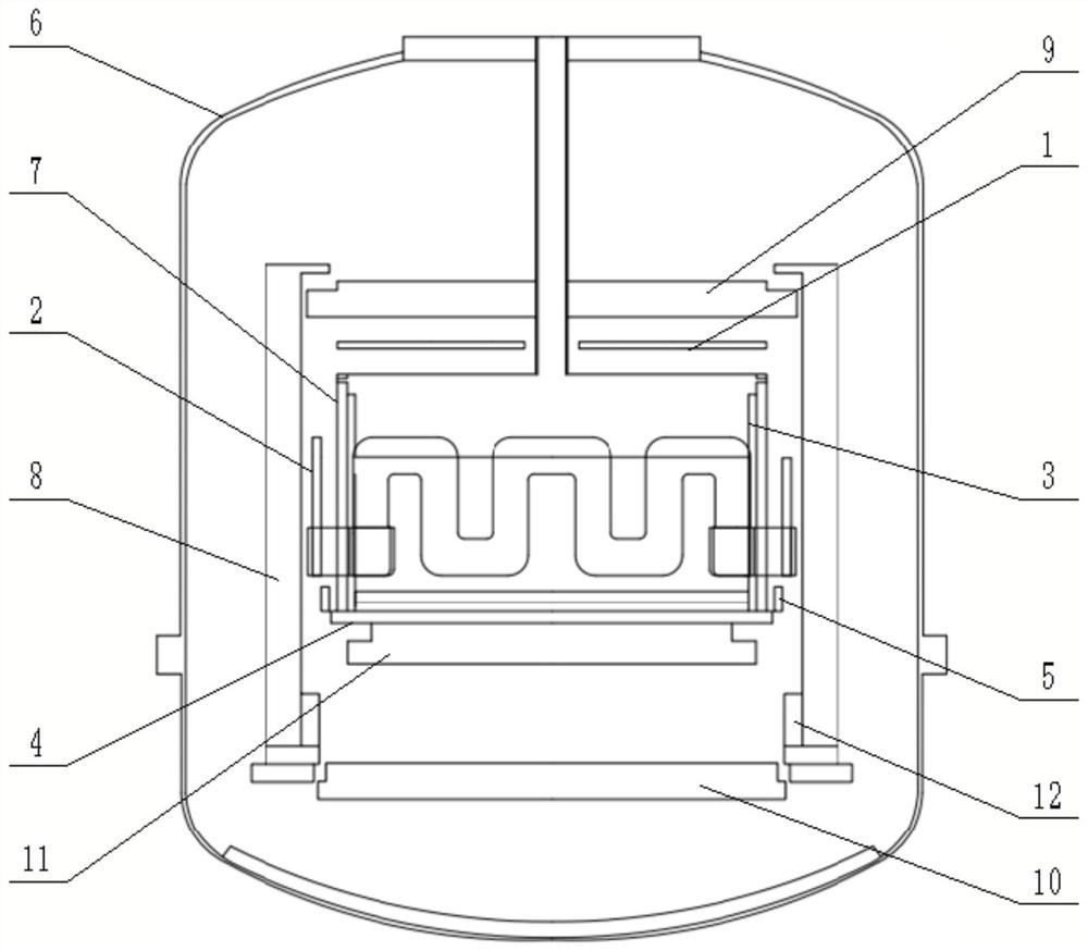
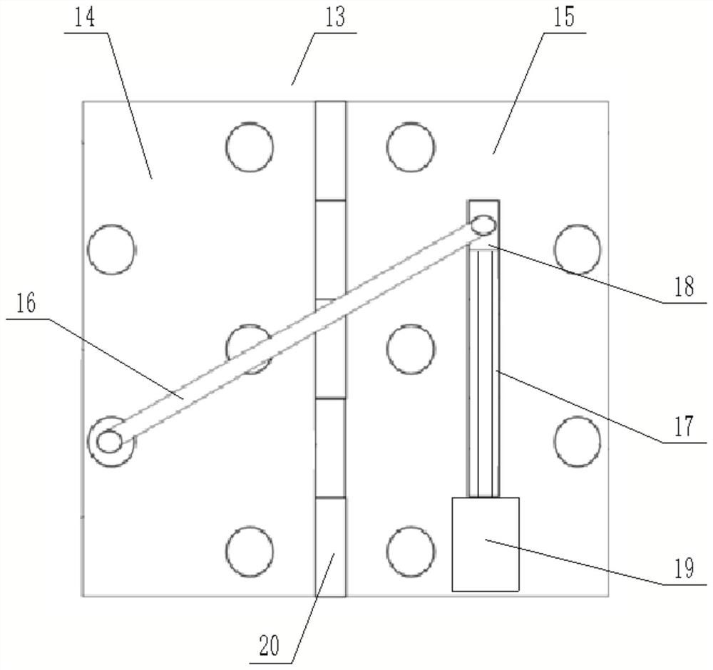
[0024] In the semi-melting high-efficiency polycrystalline ingot casting process, the crystalline silicon scrap is laid on the bottom of the quartz crucible as the seed crystal when charging. In the melting stage, the silicon material cannot be completely melted, and it is necessary to ensure a certain height of the seed crystal retention layer at the bottom. . Therefore, the first embodiment of the heat insulating block 5 is as follows: during the heating stage, the furnace temperature needs to be raised rapidly, the first hinge 14 and the second hinge 15 are in a horizontal state, and the heat insulating block 5 is placed horizontally, as figure 1 shown. The ingot furnace is divided into upper and lower areas. The area above the insulation block 5 including the top heater 1 and the side heater 2 is the hot area, and the area below the insulation block 5 including the directional heat dissipation block 11 and the water wall 12 of the furnace shell is the cold area. Since th...

Embodiment 2

[0028] During the high-efficiency full-melt polycrystalline ingot casting process, amorphous silicon / silicon-containing materials are fixed at the bottom of the quartz crucible to form a nucleation layer with a rough surface. After the silicon material is completely melted, the erosion time and intensity of the silicon melt to the nucleation layer are controlled. During crystal growth, it is necessary to control the degree of supercooling to grow high-quality polysilicon ingots. Therefore, the second embodiment of the heat insulating block 5 is as follows: during the heating stage, the furnace temperature needs to be raised rapidly, the heat insulating block 5 is placed horizontally, and the first hinge 14 and the second hinge 15 are in a horizontal state, such as figure 1 shown. The ingot furnace is divided into upper and lower areas. The area above the insulation block 5 including the top heater 1 and the side heater 2 is the hot area, and the area below the insulation blo...


PUM


Abstract

The invention discloses a polycrystalline silicon ingot furnace, which comprises a furnace body and a heat preservation cover arranged in the furnace body. A crucible, a bottom plate, a heater, a heatinsulation block and a heat exchange device are arranged in the heat preservation cover; the bottom plate is installed on the heat exchange device; the crucible is placed on the bottom plate; a crucible protection plate is installed on the outer wall of the crucible; an angle adjusting mechanism is installed on the side wall of the bottom plate; the heat insulation block is installed on the angleadjusting mechanism, and the tail end of the heat insulation block is in contact connection with the heat preservation cover. By changing the placement mode of the carbon felt heat insulation block,namely adjusting the included angle between the carbon felt heat insulation block and the bottom graphite protection plate, the heat dissipation path and mode can be effectively controlled, and the regulation and control of a thermal field are realized, so that different requirements of each process of ingot casting are met.

Description

technical field [0001] The invention relates to the technical field of solar photovoltaic industry, in particular to a polycrystalline silicon ingot furnace. Background technique [0002] Directional solidification is the mainstream technology for preparing solar crystalline silicon in the photovoltaic industry. In the ingot casting furnace, graphite heaters arranged on five sides of the top side are usually used as the heating system, and the side insulation cage around the side heaters is lifted up and down to make the silicon material in the crucible and the directional heat dissipation block, graphite support column, furnace The shell and other components dissipate heat through heat conduction or radiation, so that a specific temperature gradient is formed in the crucible, and the silicon material grows directionally from bottom to top. In order to reduce the dislocation density of silicon ingots and improve the quality of silicon ingots, various new ingot casting techn...

Claims


Application Information

Patent Timeline
IPC IPC(8): C30B28/06C30B29/06
CPCC30B28/06C30B29/06
Inventor 周继承冯天舒
Owner CENT SOUTH UNIV
Why Eureka
Try Eureka