Burner and flame temperature control method

A flame temperature and burner technology, applied in the burner control device, combustion method, burner and other directions, can solve the problem of high temperature of the flame ejected from the burner, avoid overheating and melting, reduce the difficulty of operation and the effect of scrap rate

Active Publication Date: 2017-02-15
张旭
View PDF4 Cites 0 Cited by
  • Summary
  • Abstract
  • Description
  • Claims
  • Application Information

AI Technical Summary

Problems solved by technology

[0006] In order to solve the problem of high temperature of the flame sprayed by the burner in the prior art, the embodiment of the present invention provides a burner and a flame temperature control method

Method used


Image

  • Burner and flame temperature control method
  • Burner and flame temperature control method
  • Burner and flame temperature control method

Examples


Embodiment 1

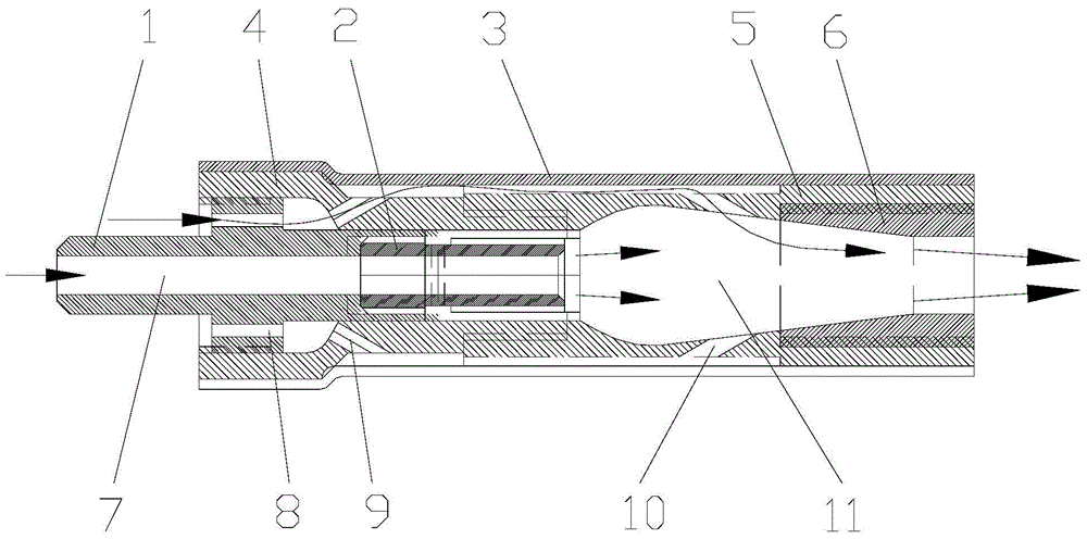
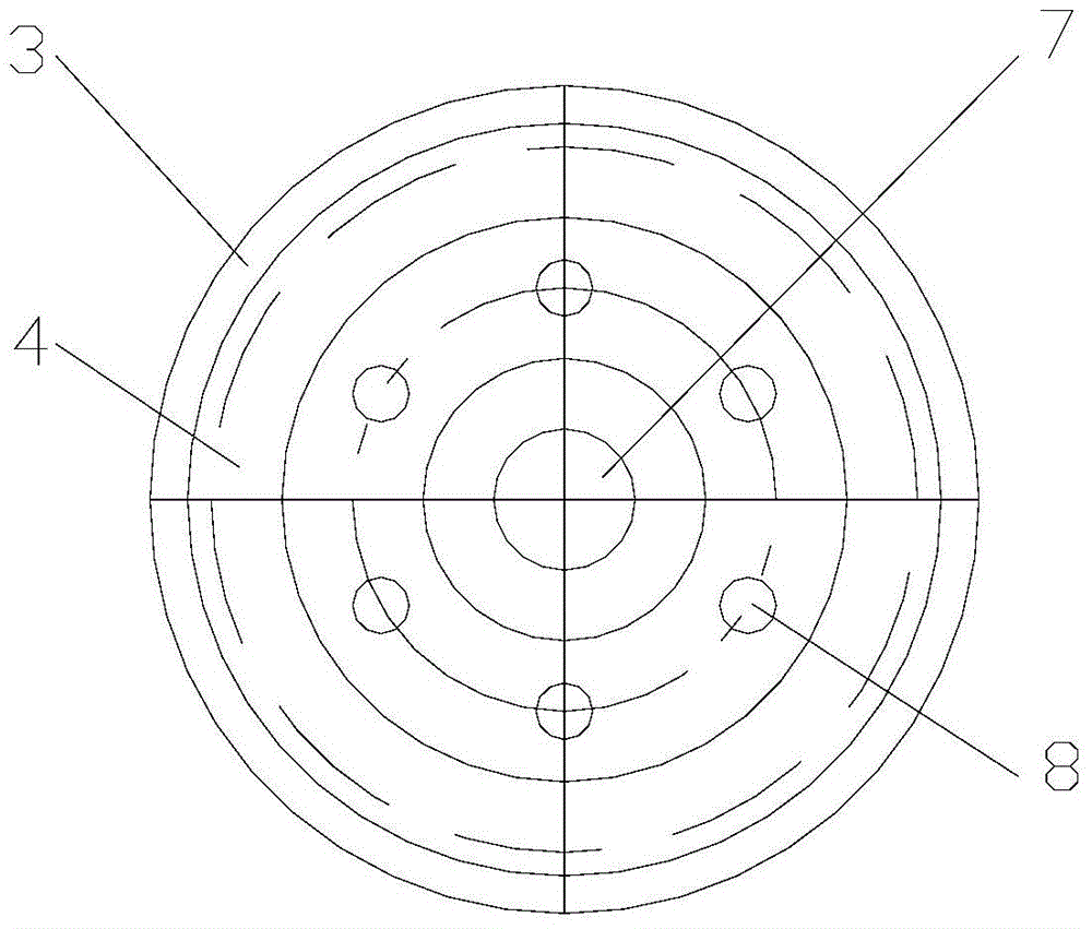
[0027] Such as figure 1 As shown, the embodiment of the present invention provides a burner, which includes a flow divider 1, a burner 2 and a casing 3, and the flow divider 1 is provided with a gas through hole 7 and at least one cold air flow hole 8 , one end of the flow divider 1 is arranged outside the housing to communicate with the gas pipeline, the other end of the flow divider 1 and the burner 2 are both arranged inside the shell 3, and the flow divider 1 and the The interior of the burner 2 is connected, and the gas enters the gas through hole 7 from the gas pipeline, enters the burner 2 through the gas through hole 7, and burns in the shell 3 after being ignited by the burner 2 to form Flame air flow, the cold air flow enters the interior of the casing 3 from the cold air flow hole 8, and is outside the gas passage 7 and the burner 2, and passes between the flow divider 1 and the casing 3 The gap between the burner 2 and the shell 3 is mixed with the flame air flow ...

Embodiment 2

[0036] An embodiment of the present invention provides a flame temperature control method, the method comprising: passing gas into the gas through hole of the flow divider, the gas enters the gas through hole and ignites and burns through the burner to form a flame flow, and the cold gas The cold air flows into the cold air flow hole of the flow divider, and the cold air flow enters the interior of the shell through the cold air flow hole and mixes with the flame air flow to reduce the temperature of the flame air flow to form a low temperature flame air flow.

[0037] As a preference, the cold airflow adopts a mixed gas of air and nitrogen. When the cold airflow is mixed with the flame airflow, the oxygen in the air can play a certain combustion-supporting effect on the combustion of the gas. Since the cold airflow contains inert gas, it ensures The shape of the flame also plays a protective role, reducing the oxygen content in the environment and reducing the oxidation of the...

Embodiment 3

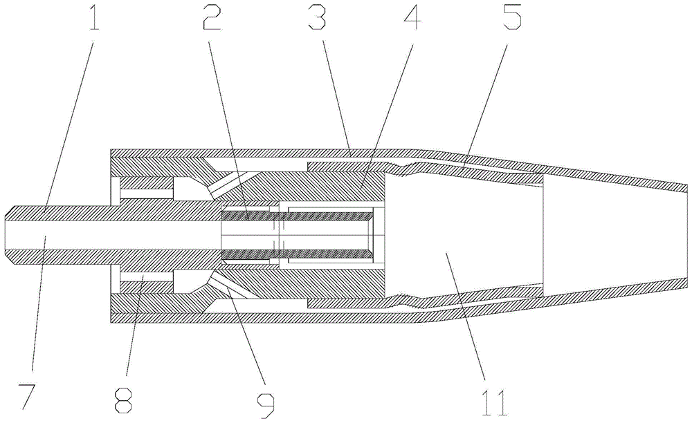
[0041] Such as image 3 As shown, the embodiment of the present invention provides a burner, the outlet nozzle 6 of the burner and the shell 3 are designed as an integral structure, that is, the shell 3 is designed to be a structure with a smaller diameter along the direction in which the flame flow is ejected, reducing The outlet nozzle 6 is eliminated, so that the structure of the burner is simpler and the processing cost is lower.


PUM


Abstract

The invention discloses a burner and a flame temperature control method and belongs to the technical field of burning. The burner comprises a flow divider, a nozzle and a housing, wherein a gas through hole and a cold gas flow through hole are formed in the flow divider; the gas through hole is communicated with the nozzle; the cold gas flow through hole is communicated with the interior of the housing; gas burns to form a flame gas flow after ignited by the nozzle; a cold gas flow enters the housing from the cold gas flow through hole and is mixed with the flame gas flow, so that the temperature of the flame gas flow is reduced; and the flame gas flow is ejected out of the housing. The flame temperature control method comprises the steps of supplying the cold gas flow into the flame gas flow to reduce the temperature of the flame gas flow, and forming a low temperature flame gas flow. The burner is provided with the flow divider to separate the gas flow from the cold gas flow, and supplies the cold gas flow into the flame gas flow to cool the flame gas flow to obtain the low temperature flame gas flow; when the burner is applied in the field of braze welding for metals with lower melting points, overheating and melting of parent metals due to the higher flame temperature are avoided; and the operation difficulty and a rejection rate of the braze welding are reduced.

Description

technical field [0001] The invention relates to the technical field of combustion, in particular to a burner and a flame temperature control method. Background technique [0002] A burner is a general term for devices that mix and burn fuel or gas with air, and then emit flames. Burners are divided into industrial burners, burners, civil burners, and special burners according to types and application fields. [0003] Most of the existing burners consist of a body, a nozzle, a gas inlet and a gas pipe. The nozzle, the gas inlet and the gas pipe are all arranged inside the body, and the gas inlet and the nozzle are connected through the gas pipe, and the gas enters the gas pipe from the gas inlet, and Flame is emitted from it after burning. [0004] In the process of realizing the present invention, the inventor finds that there are at least the following problems in the prior art: [0005] In the existing burner, the temperature of the flame sprayed out after gas combustio...

Claims


Application Information

Patent Timeline
Patent Type & Authority Patents(China)
IPC IPC(8): F23D14/00F23D14/46
CPCF23D14/40F23D14/46F23D2203/00F23D2208/00
Inventor 张旭
Owner 张旭
Why Eureka
Try Eureka