Tool magazine of machine tool

A tool library and tool technology, applied in the direction of manufacturing tools, tool changing devices, comprehensive factory control, etc., can solve the problems of not being able to accommodate various types of tools, increasing tool replacement time, reducing machine tool reliability, etc. Processing time, the pursuit of compactness, the effect of improving stability and reliability

Active Publication Date: 2020-09-11
DN SOLUTIONS CO LTD
View PDF10 Cites 2 Cited by
  • Summary
  • Abstract
  • Description
  • Claims
  • Application Information

AI Technical Summary

Problems solved by technology

[0017] However, if image 3 As shown, the tool stock of the conventional machine tool has the following problem, that is, when the inner diameter tool holder 5 combined with the inner diameter tool 6 and the outer diameter tool holder 7 combined with the outer diameter tool 8 are arranged adjacent to each other, due to interference with the workpiece 2, etc., the Collisions occur, and in order to prevent such collisions, the workers have to change the inner diameter tool and the outer diameter tool at any time, so the productivity of the machine tool is reduced, causing inconvenience to the workers
[0018] In addition, since the tool library of the existing machine tool only has a directional tool (vertical direction in the case of inner diameter tools, horizontal direction in the case of outer diameter tools), and cannot accommodate various types of tools, there is Leading to the large-scale of the tool library, and finally the problem of not being able to miniaturize the machine tool
[0019] In addition, when the vertical turning center is moved horizontally or vertically, there is a tool change time for performing the corresponding process because the tool magazine of the existing machine tool only has tools in one direction (inner diameter tool or outer diameter tool) Increased productivity decreases, and the reliability of the machine tool decreases

Method used


Image

  • Tool magazine of machine tool
  • Tool magazine of machine tool
  • Tool magazine of machine tool

Examples


Embodiment Construction

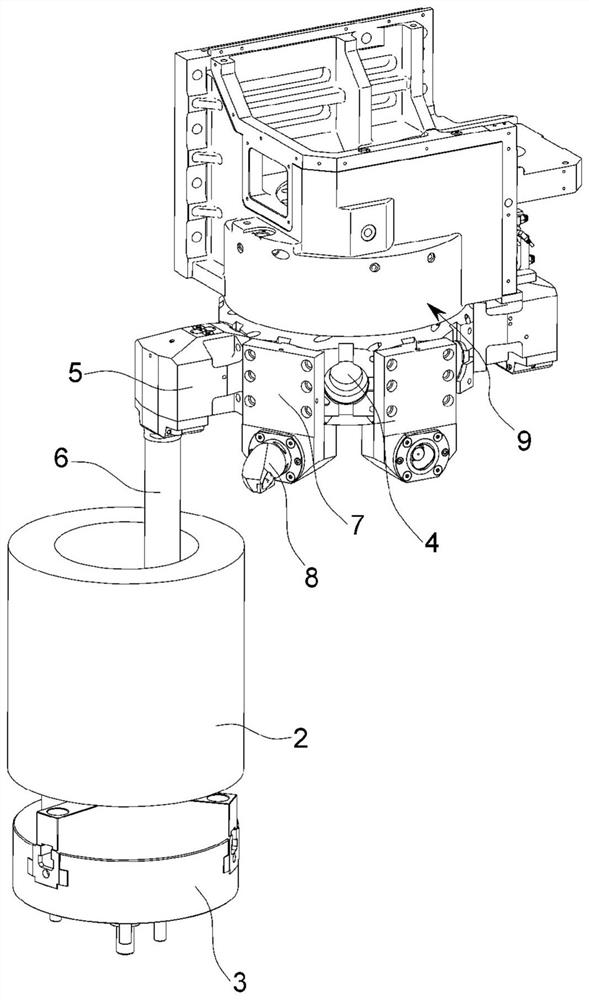
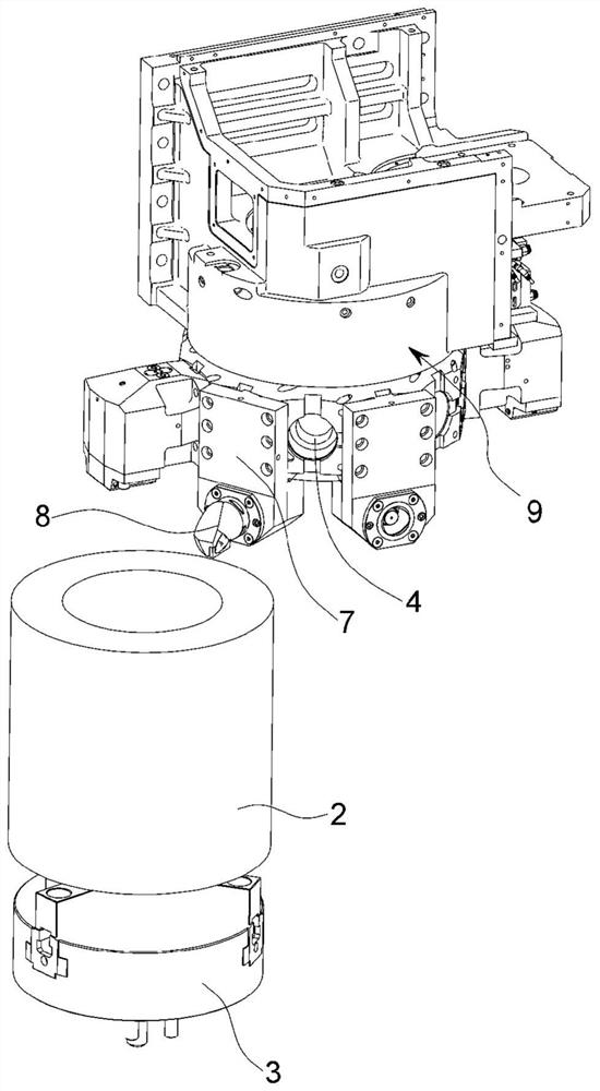
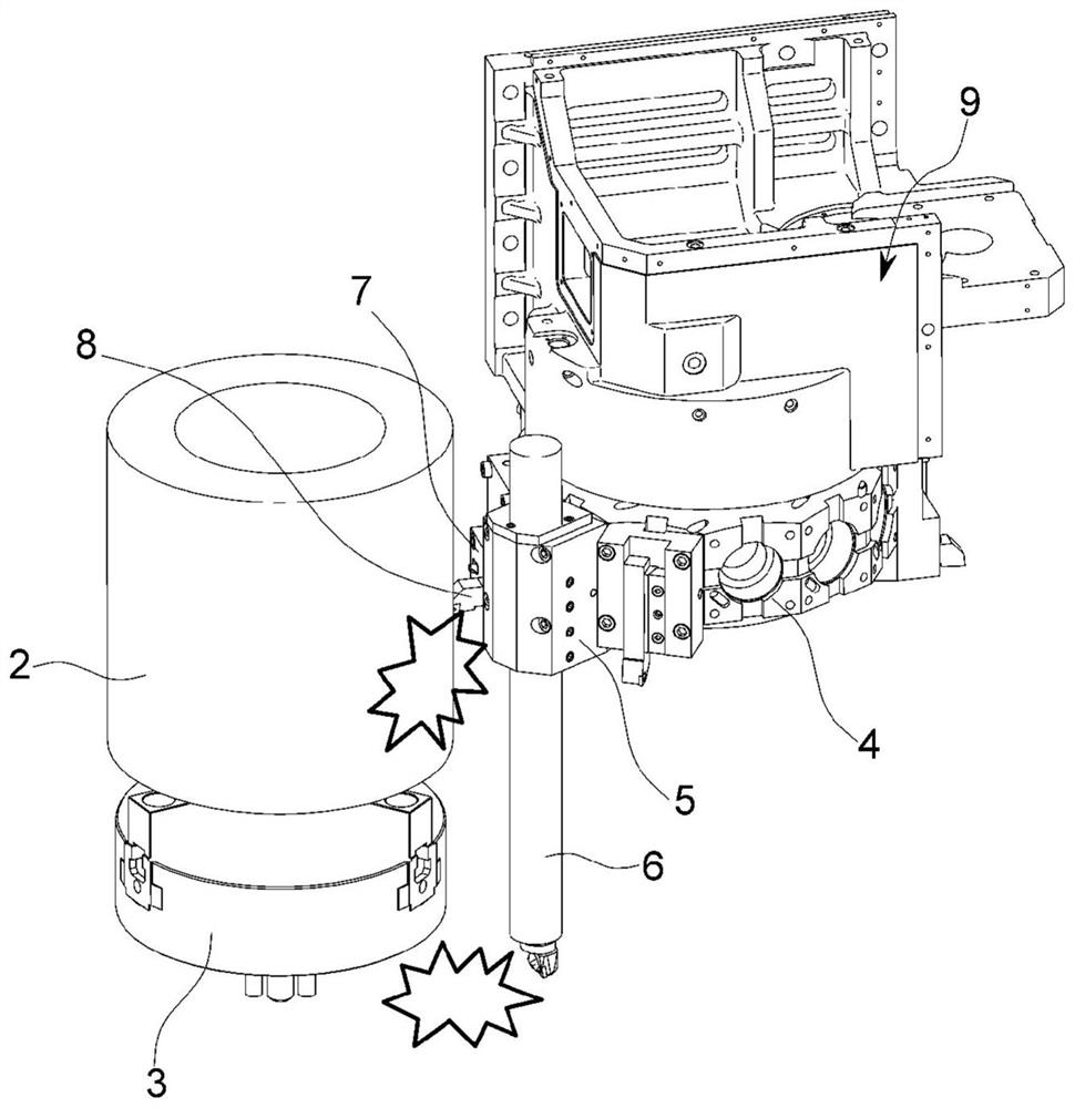
[0045] Next, a detailed description will be given with reference to a diagram of a tool magazine of a machine tool according to an embodiment of the present invention. The embodiments described below are provided as examples to fully convey the idea of ​​the present invention to those skilled in the art. Therefore, the present invention is not limited to the embodiments described below, but can be embodied in other forms. In addition, in the drawings, the size, thickness, etc. of the device may be shown enlarged for convenience. Throughout the specification, the same symbols denote the same constituent elements.

[0046] The advantages, characteristics, and means for achieving these of the present invention will be clarified by the accompanying drawings and the embodiments described later. However, the present invention is not limited to the following examples, and can be embodied in other various forms. This embodiment is used to make the disclosure of the present inventio...


PUM


Abstract

The present invention relates to a tool magazine of a machine tool, comprising: a base part installed in a part of a space in which a spindle head moves; a support part installed vertically with respect to the base part; a rotation shaft part rotatably installed to the support part; a first tool storage part rotatably installed to the rotation shaft part, and accommodating a plurality of tools radially from the center of rotation of the rotation shaft part; and a second tool storage part which is vertically above the first tool storage part and rotatably installed to the rotation shaft part, and accommodates a plurality of tools radially from the center of rotation of the rotation shaft part, wherein the tool magazine of a machine tool may be installed such that the tool storage directionof the second tool storage part is orthogonal to the tool storage direction of the first tool storage part. Moving in the horizontal and vertical directions, the spindle head easily replaces the inner-diameter tools in the first tool storage part and the outer-diameter tools in the second tool storage part, thereby minimizing non-processing time and enhancing the productivity of the machine tool.

Description

technical field [0001] The present invention relates to a tool magazine for a machine tool, and in more detail, to a tool receiving portion formed with a multi-layer tool magazine in a vertical turning center, which can easily change the inner diameter when the spindle head moves in the horizontal direction and the vertical direction Tool library for machine tools and OD tools. Background technique [0002] Generally, a machine tool refers to a machine used for the purpose of processing metal / non-metal workpieces into the required shape and size by using appropriate tools through various cutting or non-cutting methods. [0003] Various machine tools such as turning centers, vertical / horizontal machining centers, portal machining centers, switch turns, electrical discharge machining machines, horizontal NC drilling machines, CNC lathes, and compound processing machines are used in various industrial sites according to the purpose of the corresponding operations. Widely used....

Claims


Application Information

Patent Timeline
Patent Type & Authority Applications(China)
IPC IPC(8): B23Q3/155
CPCB23Q3/15722B23Q3/15539B23Q2003/15586B23Q3/15534B23Q3/15503B23Q2003/15532Y10T483/1882Y10T483/1795B23Q3/15753B23Q3/15506B23Q3/15566B23Q3/15706
Inventor 周泰焕
Owner DN SOLUTIONS CO LTD
Why Eureka
Try Eureka