
Bridge gap detection equipment with depth structure for bridge maintenance

A technology for testing equipment and bridges, applied in measurement devices, using re-radiation, radio wave measurement systems, etc., can solve the problems of inability to adjust the detection angle flexibly, easily affected by subjective factors, and large bridge detection vehicles. The effect of offset, stable placement, and low manufacturing cost

Pending Publication Date: 2020-09-01
广东中林建筑园林工程有限公司
View PDF11 Cites 10 Cited by
  • Summary
  • Abstract
  • Description
  • Claims
  • Application Information

AI Technical Summary

Problems solved by technology

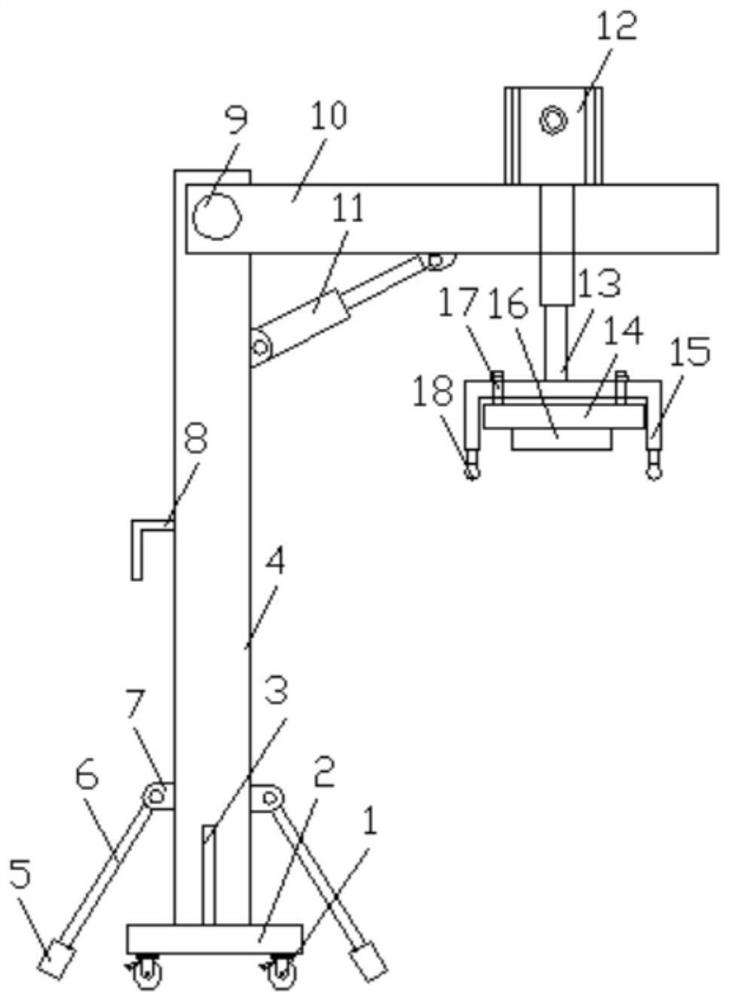
Manual inspection is mainly to observe the cracks at the bottom of the bridge through a telescope, or to observe the cracks on the bottom of the bridge with the naked eye at close range by building a platform at the bottom of the bridge, record the length and width of the cracks, and judge the growth of cracks through multiple inspections However, this detection method relies on personal experience, is easily affected by subjective factors, and has low detection efficiency; the bridge inspection vehicle mainly moves along the extension direction of the bridge, uses the camera to take pictures, and judges whether there are cracks. The detection accuracy depends on the accuracy of image matching, the requirements for the camera are very high, and the bridge inspection vehicle is large in size, the detection angle cannot be adjusted flexibly, and the detection range has certain limitations. In order to solve the above problems, a bridge is designed. Bridge gap detection equipment with deep structure for maintenance

Method used


Image

  • Bridge gap detection equipment with depth structure for bridge maintenance
  • Bridge gap detection equipment with depth structure for bridge maintenance
  • Bridge gap detection equipment with depth structure for bridge maintenance

Examples


Embodiment Construction

[0016] The following will clearly and completely describe the technical solutions in the embodiments of the present invention with reference to the accompanying drawings in the embodiments of the present invention. Obviously, the described embodiments are only some, not all, embodiments of the present invention. Based on the embodiments of the present invention, all other embodiments obtained by persons of ordinary skill in the art without making creative efforts belong to the protection scope of the present invention.

[0017] In the description of the present invention, it should be noted that the orientation or positional relationship indicated by the terms "vertical", "upper", "lower", "horizontal" etc. is based on the orientation or positional relationship shown in the drawings, and is only In order to facilitate the description of the present invention and simplify the description, it does not indicate or imply that the device or element referred to must have a specific o...


PUM


Abstract

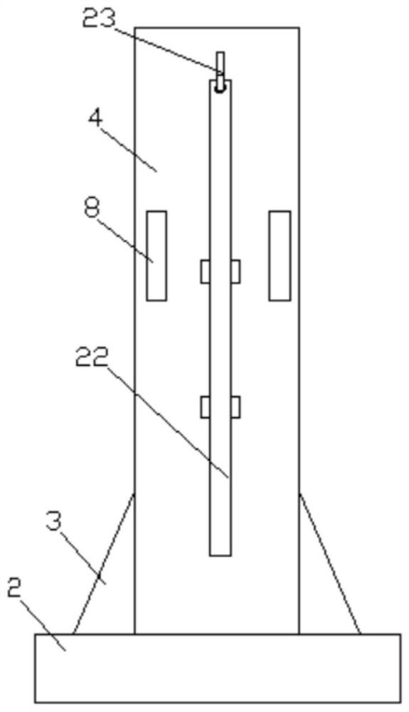
The invention relates to the technical field of bridge detection, and specifically discloses bridge gap detection equipment with a depth structure for bridge maintenance. The equipment comprises a base, side plates, a mounting plate, a protective cover and a detection table; the top center of the base is fixedly connected with the bottom ends of side plates; the top ends of the side plates are rotationally connected with mounting plates through rotating shafts; electric push rods are arranged between two sides of the bottom of the mounting plate and the side plates; a supporting plate is arranged in a cavity in the top of the mounting plate, rotating rods are arranged at the upper end and the lower end of the supporting plate, one end of each rotating rod penetrates through a through holeof the mounting plate and then is in threaded connection with a butterfly nut, and an air cylinder is arranged at the top of the supporting plate and connected with a hydraulic telescopic rod which isconnected with a protective cover. The detection equipment is convenient to move and carry and stable to place during detection; the installation angle of the detector can be flexibly adjusted at multiple angles, the bridge gap measuring range is wide, the equipment manufacturing cost is low, practicability is high, and the detector is suitable for application and popularization.

Description

technical field [0001] The invention relates to the technical field of bridge detection, in particular to bridge gap detection equipment with a deep structure for bridge maintenance. Background technique [0002] Cracks on the surface of the bridge mean that structural damage has occurred inside the bridge, and outside water vapor can easily enter the interior of the bridge, thereby accelerating the corrosion of steel bars, which in turn leads to a decrease in the bearing capacity of the bridge, seriously affecting people's safe travel. Therefore, capturing and inspecting cracks on the surface of bridges in time is of great significance for predicting or discovering engineering dangers in time, ensuring reliable operation of bridges and prolonging the service life of bridges. Bridge inspection in the prior art mainly includes two methods: manual inspection and bridge inspection vehicle inspection. Manual inspection is mainly to observe the cracks at the bottom of the bridge...

Claims


Application Information

Patent Timeline
IPC IPC(8): G01N21/88G01S13/88
CPCG01N21/8851G01S13/885G01N2021/8874
Inventor 刘祥城林泽雄肖映芬
Owner 广东中林建筑园林工程有限公司
Learn More