A method of manufacturing a multilayer chip power inductor

A production method and technology of power inductors, which are applied in the manufacture of inductors/transformers/magnets, circuits, coils, etc., can solve the problems of limiting the saturation current of laminated power inductors, easy magnetization saturation, and poor DC superposition characteristics, and achieve low eddy current Effects of loss, high magnetic permeability, and high oxidation resistance

Active Publication Date: 2021-11-30
SHENZHEN MICROGATE TECH
View PDF4 Cites 0 Cited by
  • Summary
  • Abstract
  • Description
  • Claims
  • Application Information

AI Technical Summary

Problems solved by technology

[0003] The magnetic material of laminated power inductors is generally soft ferrite powder, which has the characteristics of high magnetic permeability and good insulation, but has the disadvantages of extremely poor DC superposition characteristics and easy magnetization saturation, which largely limits the strength of laminated power inductors. Saturation current of power inductor

Method used


Image

  • A method of manufacturing a multilayer chip power inductor
  • A method of manufacturing a multilayer chip power inductor
  • A method of manufacturing a multilayer chip power inductor

Examples


preparation example Construction

[0039] A kind of soft magnetic composite slurry, the preparation method of described soft magnetic composite slurry comprises the following steps:

[0040] The first step is pre-baking, respectively baking the iron-based alloy powder and ferrite powder at 80°C-130°C;

[0041] The second step is to disperse, add grinding medium to the ball mill, add 0.1-4.0wt% dispersant to the solvent, mix well, make A liquid and add it to the ball mill; take iron-based alloy powder and ferrite The powder is pre-mixed, and the pre-mixed powder is added to a ball mill tank for ball milling to make B liquid;

[0042] The third step is to make slurry, take 1-15wt% binder and 0.5-8wt% plasticizer to dissolve in the solution to make liquid C, add liquid C to the ball mill tank, and perform ball milling to make D slurry.

[0043] The iron-based alloy powder is selected from at least one of Fe-Si-Al, Fe-Si-Cr, and Fe-Cr-Al, with an average particle size of 2-30 μm, and the iron-based alloy powder i...

Embodiment 1

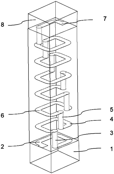
[0064] Embodiment 1: Reference figure 1 and Figure 15 , the present invention is mainly composed of coils 2-6, substrate 9 and terminal electrodes 10. The coils 2-6 are designed inside the base body 9, and the lower lead-out end 2 and the upper lead-out end 7 are respectively connected to both sides of the terminal electrode 10. The coils are connected by point posts to form spiral electrodes, and the DC resistance can be reduced by increasing the thickness of the coils.

[0065] In the present embodiment, the preparation method of the soft magnetic composite slurry of the present invention is as follows: take a certain amount of (NiZn)Fe 2 o 4 and Fe-Si-Cr powder, (NiZn)Fe2O4 accounts for 15wt% of the total mass of the powder, baked at 120°C for 12 hours to remove the adsorbed water in the powder. Among them, Si content in Fe-Si-Cr powder is 3-7wt%, Cr content is 3-7wt%, (NiZn)Fe 2 o 4 The average particle size is about 0.8-1.5 μm, and the average particle size of Fe-S...


PUM

PropertyMeasurementUnit
particle sizeaaaaaaaaaa
diameteraaaaaaaaaa
thicknessaaaaaaaaaa

Abstract

The present invention relates to a manufacturing method of inductors. At present, the printing method of laminated inductors mainly adopts the method of directly printing conductive paste on the film tape. The electrode printed in this way has a large width-thickness ratio, a small magnetic flux area, and the thickness of the silver layer is difficult to increase. For this reason, the present invention provides a method for preparing soft magnetic composite slurry and a method for using the soft magnetic composite slurry to prepare laminated power inductors. The specific steps include pre-baking, dispersion and slurry production, and making a diaphragm , connection point columns, magnetic paste layers for printing internal electrodes, etc. Compared with the existing technology, the laminated power inductor manufactured by using the above-mentioned soft magnetic composite slurry and the new manufacturing method has excellent saturation characteristics and DC resistance characteristics, and it has relatively innovative materials and processes.

Description

technical field [0001] The invention relates to a manufacturing method of an inductor, in particular to a laminated chip power inductor made of soft magnetic composite slurry. Background technique [0002] With the upgrading of electronic products such as mobile phones, cameras, disk drives of notebook computers, and portable audio players, the market needs power inductors with better saturation characteristics. The market for high-efficiency DC converters and finer inductors has grown rapidly with the widespread use of high-power conversion termination components on circuit boards. [0003] The magnetic material of laminated power inductors is generally soft ferrite powder, which has the characteristics of high magnetic permeability and good insulation, but has the disadvantages of extremely poor DC superposition characteristics and easy magnetization saturation, which largely limits the strength of laminated power inductors. The saturation current of the power inductor. ...

Claims


Application Information

Patent Timeline
Patent Type & Authority Patents(China)
IPC IPC(8): H01F41/02H01F41/04H01F41/10H01F1/44
CPCH01F1/44H01F41/02H01F41/043H01F41/10
Inventor 熊春美梁启新侯志华简立勇马龙周志斌樊应县
Owner SHENZHEN MICROGATE TECH
Why Eureka
Try Eureka