
Composite type energy absorbing device with thin-wall metal tube filled based on cut honeycomb structure

A honeycomb structure and energy-absorbing device technology, applied in the direction of shock absorbers, springs, springs/shock absorbers, etc., can solve the problems of high blade material and processing technology requirements, difficult energy absorption control, and single energy absorption method. Achieve low blade material and shape requirements, facilitate the evaluation of energy absorption effect, and achieve good energy absorption effect

Active Publication Date: 2020-08-25
NAT UNIV OF DEFENSE TECH
View PDF7 Cites 3 Cited by
  • Summary
  • Abstract
  • Description
  • Claims
  • Application Information

AI Technical Summary

Problems solved by technology

[0005] The technical problems to be solved by the present invention are single energy absorption mode, no over-range impact load protection, high requirements for cutting energy absorption on blade material and processing technology, difficulty in compound sequential energy absorption control, and excessive acceleration caused by peak stress and other problems, a new composite energy-absorbing device is provided

Method used


Image

  • Composite type energy absorbing device with thin-wall metal tube filled based on cut honeycomb structure
  • Composite type energy absorbing device with thin-wall metal tube filled based on cut honeycomb structure
  • Composite type energy absorbing device with thin-wall metal tube filled based on cut honeycomb structure

Examples


Embodiment Construction

[0029] In order to more clearly illustrate the technical solutions in the embodiments of the present invention, the following will introduce the drawings that need to be used in the embodiments or the description of the prior art. Obviously, the drawings in the following description are only part of the implementation of the present invention example, not all examples. Based on the embodiments of the present invention, those skilled in the art can also obtain other drawings based on these drawings without any creative effort.

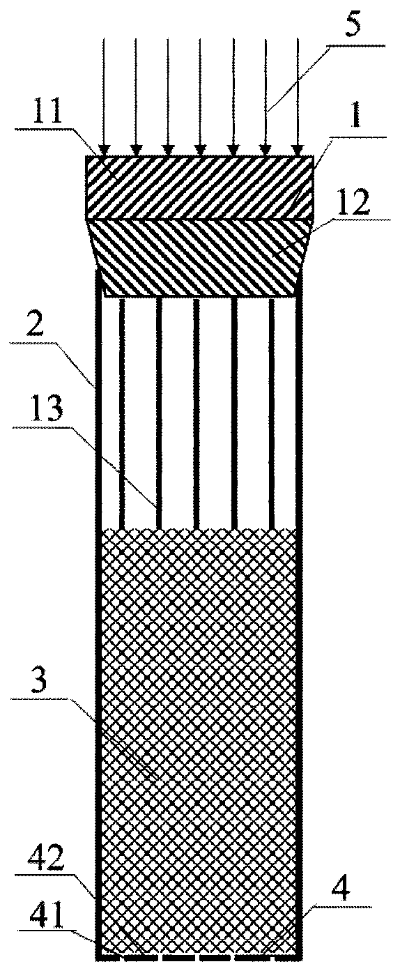
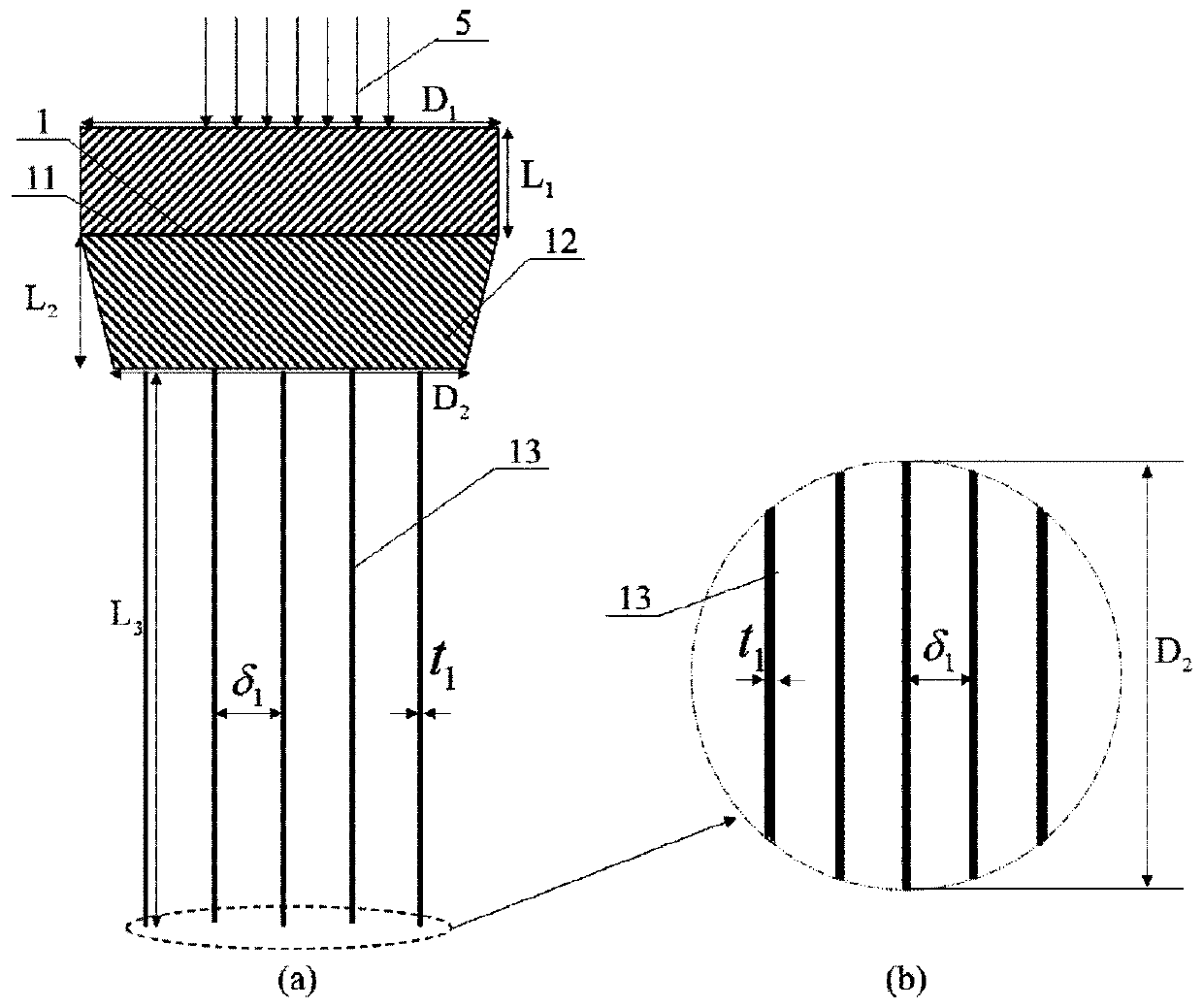
[0030] figure 1 It is a partial sectional view of the overall structure of the present invention. Such as figure 1 As shown, the compound energy-absorbing device of the present invention based on the cut honeycomb structure filled with thin-walled metal pipes consists of a wedge-shaped expansion block 1, a thin-walled metal pipe 2, a honeycomb structure 3, and a gas leakage protection chassis 4.

[0031] figure 2 for figure 1 Middle AA' sectional ...


PUM

PropertyMeasurementUnit
Yield strengthaaaaaaaaaa
Densityaaaaaaaaaa
Yield strengthaaaaaaaaaa

Abstract

The invention discloses a composite type energy absorbing device with a thin-wall metal tube filled based on a cut honeycomb structure. The problems that an energy absorbing device is single in energyabsorbing manner, and overrange impact load protection cannot be achieved can be solved. The device is composed of a wedge-shaped diameter expansion block with a parallel blade set, the thin-wall metal tube, the honeycomb structure and an air leakage protection chassis, an inner cavity of the thin-wall metal tube is coaxially filled with the honeycomb structure, the wedge-shaped diameter expanding block is coaxially and tangently placed on an upper port of the thin-wall metal tube, the air leakage protection chassis is coaxially welded to a lower port of the thin-wall metal tube, an air leakage groove of the chassis coincides with a blade face of the wedge-shaped diameter expanding block, when the wedge-shaped diameter expanding block bears conventional impact loads, the parallel blade set generates cutting energy absorbing on the honeycomb structure, the metal tube generates diameter expanding plastic energy absorbing, when the wedge-shaped diameter expanding block bears the overrange impact load, the honeycomb structure generates buckling plastic energy absorption, low-acceleration response and the overrange impact load protection of a vehicle during conventional collision can be achieved, the energy absorbing effect is good, and key parts can be repeatedly used.

Description

technical field [0001] The invention relates to the technical field of passive safety impact energy-absorbing devices, in particular to an impact-protective energy-absorbing device based on a cut honeycomb structure filled thin-walled metal tube under the combined action mechanism of cutting, diameter expansion and buckling. Background technique [0002] Energy-absorbing devices are widely used in impact environments. Especially with the development of high-speed traffic, energy-absorbing devices are an important part of ensuring vehicle safety. They can absorb collision kinetic energy through changes in their own structures, thereby protecting personnel's lives. For this reason, the traffic department sets the fatal acceleration or threshold acceleration of traffic accidents as 5000m / s 2 . When the acceleration response exceeds this threshold during the collision impact, the life of the personnel may be in danger. This puts higher requirements on the low acceleration resp...

Claims


Application Information

Patent Timeline
IPC IPC(8): F16F7/12
CPCF16F7/121F16F7/123F16F7/127F16F7/128F16F2224/02
Inventor 李翔城林玉亮卢芳云李翔宇陈荣张玉武彭永梁民族
Owner NAT UNIV OF DEFENSE TECH
Learn More