Robot joint part with cooling structure, power joint and robot

A technology of robot joints and heat dissipation structure, which is applied in the field of robots, can solve the problems of excessive external liquid cooling auxiliary devices, large output loads of robot power joints, compact structure size, and low heat dissipation efficiency, so as to speed up speed and heat exchange efficiency, eliminate Heat accumulation, good cooling effect

Active Publication Date: 2020-08-25
BEIJING INSTITUTE OF TECHNOLOGYGY
View PDF11 Cites 4 Cited by
  • Summary
  • Abstract
  • Description
  • Claims
  • Application Information

AI Technical Summary

Problems solved by technology

In this way, the heat dissipation efficiency is low, and it can only meet the requirements of general application conditions with low requirements, and is not suitable for dynamic joints with large moments.
[0003] In addition, some designers apply the liquid cooling method to the power joint. The liquid cooling method is generally to install a liquid flow channel in the power joint, and to take away the heat generated by the motor through the circulation of the liquid. This method needs to connect the liquid flow channel to the An external liquid cooling device is used to realize liquid circulation. For example, a liquid cooling channel is reserved in the motor casing and a liquid cooling circulation device is connected externally. Although the heat dissipation efficiency of this liquid cooling method is better than that of joints without heat dissipation, it often requires more A large external heat dissipation circulation device will result in a large dynamic joint size and is not conducive to installation
[0004] Whether it is the existing heat conduction heat dissipation method of the joint components itself, or the liquid cooling method, these heat dissipation methods can no longer meet the needs of the robot's continuous demand for greater force load and smaller volume of the power joint unit.
That is to say, although the existing power joint heat dissipation method can meet the general heat dissipation performance requirements, it cannot cope with the working conditions that customers gradually expect such as continuous large torque output or high explosive overload, or there are too many external liquid cooling auxiliary devices, and the impact is slow and other problems, it cannot meet the requirements of higher output load of robot dynamic joints and compact structure size
[0005] With the continuous improvement of the continuous high torque, high explosive force, and high overload capabilities of various robots at present, the load on the power joints and the motor is increasing, which causes the problem of motor heat accumulation. With the continuous output of the motor, it is If the accumulated heat cannot be effectively dissipated, it will affect the stability of the motor and dynamic joints

Method used


Image

  • Robot joint part with cooling structure, power joint and robot
  • Robot joint part with cooling structure, power joint and robot
  • Robot joint part with cooling structure, power joint and robot

Examples


Embodiment Construction

[0035] In order to make the purpose, technical solutions and advantages of the embodiments of the present invention more clear, the embodiments of the present invention will be further described in detail below in conjunction with the accompanying drawings. Here, the exemplary embodiments and descriptions of the present invention are used to explain the present invention, but not to limit the present invention. In the drawings of the present invention, the same reference numerals represent the same or similar components.

[0036] Here, it should be noted that, in order to avoid obscuring the present invention due to unnecessary details, only the structures and / or processing steps that are closely related to the solution according to the present invention are shown in the drawings, while those related to the present invention are omitted. Invent other details that don't really matter.

[0037] It should be emphasized that the term "comprises / comprises / has" when used herein ref...


PUM


Abstract

The invention provides a robot joint part with a cooling structure, a power joint and a robot. The joint part is provided with a hollow cylindrical structure and sleeves the outer side of a heat source part, the joint part is provided with multiple phase change cooling units, each phase change cooling unit is distributed in the axial direction of a cylinder wall, each phase change cooling unit comprises a phase change working medium, a capillary material and a seal phase change cavity, the phase change working medium is located in the phase change cavity, the interior of the phase change cavity is in a vacuum or negative pressure environment, the capillary material is located on the inner cavity wall of the phase change cavity, cooling auxiliary ribs are mounted on the periphery of the cylinder wall of the joint part and located on the side, away from the heat source part, of each phase change cooling unit, multiple airflow channels are formed by the cooling auxiliary ribs in a definedmanner, the cross sections of the formed airflow channels are gradually reduced in the airflow direction, the airflow is accelerated to flow in the airflow channels, the joint part is good in coolingeffect, and high in heat conduction efficiency, heat gathering of the joint power source can be rapidly removed, and the power joint of the robot is kept structurally compact.

Description

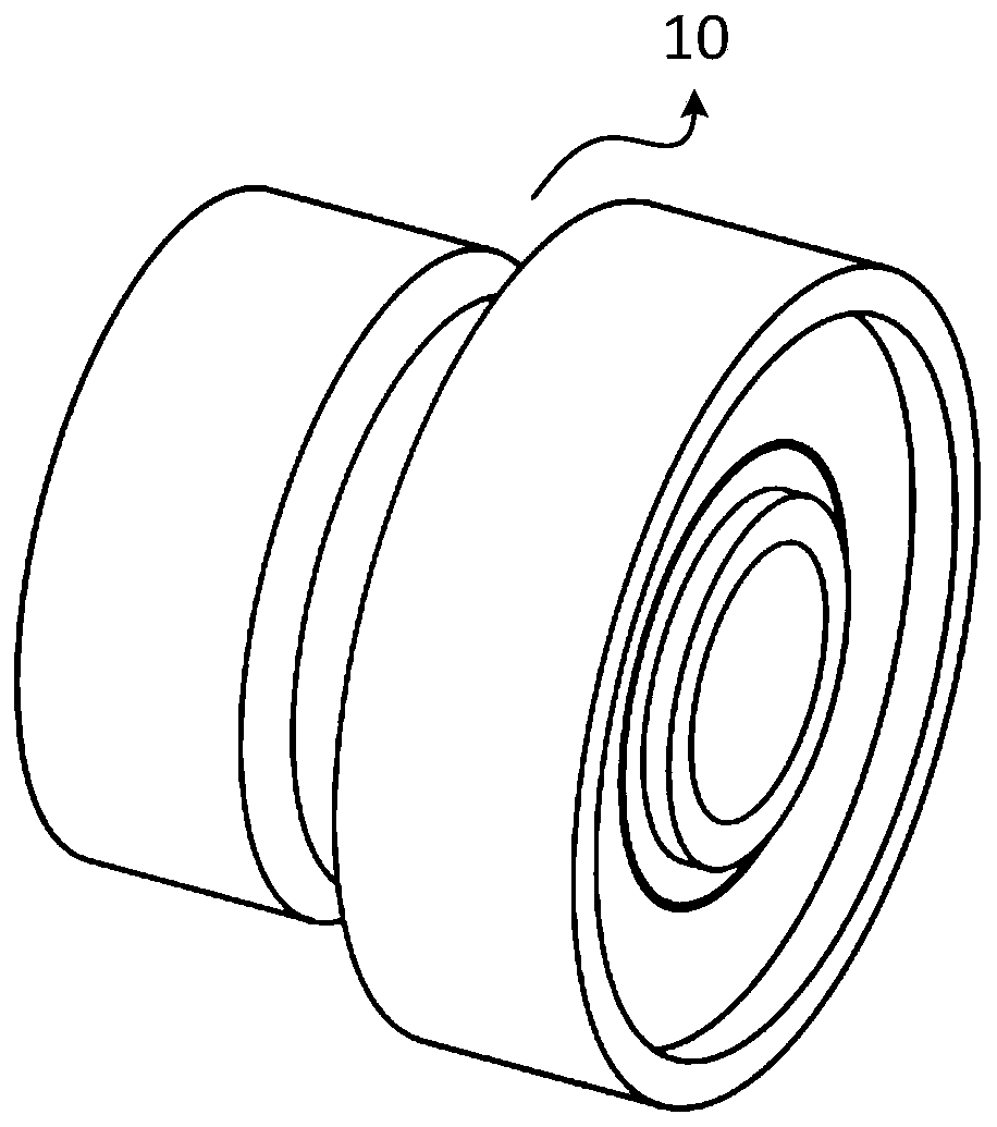
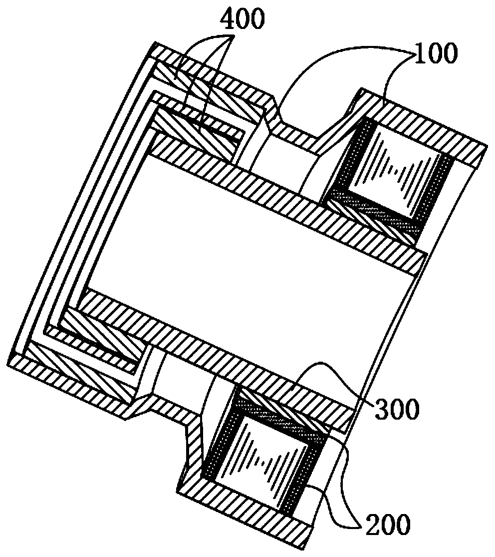
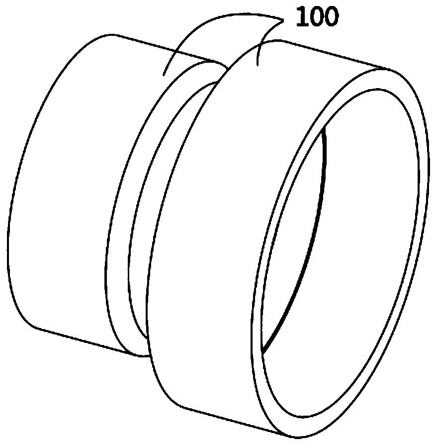
technical field [0001] The invention relates to the technical field of robots, in particular to a robot joint component with a heat dissipation structure, a dynamic joint and a robot. Background technique [0002] Such as figure 1 , figure 2 and image 3 As shown, the power joint 10 of the robot generally includes a motor 200, a reducer 400 and a joint member 100. The motor 200 and the reducer 400 are installed in the hollow joint member 100. The power joint is powered by the motor 200 and rotates to provide a power source. The motor 200 and The speed reducer 400 is connected to the transmission through the transmission shaft 300 , and after being converted by the speed reducer 400 , the rotational speed is reduced to increase the output torque. The joint member 100 provides support, heat dissipation and installation configuration for each component. The motor is the main heat source of the joint, and the heat needs to be transferred to the outside of the power joint thr...

Claims


Application Information

Patent Timeline
Patent Type & Authority Applications(China)
IPC IPC(8): B25J17/00B25J19/00
CPCB25J17/00B25J19/0054B25J9/102
Inventor 黄强张武邱东霖余张国刘兴中
Owner BEIJING INSTITUTE OF TECHNOLOGYGY
Why Eureka
Try Eureka