Double-blowing molten iron desulfurization device

A hot metal desulfurization and injection device technology, applied in the field of hot metal treatment, can solve problems such as complex structure of hot metal desulfurization devices, inability to form high-efficiency complementarity, and accumulation of desulfurizing agents, so as to eliminate the accumulation of desulfurizing agents, improve dynamic conditions, and increase utilization rate effect

Inactive Publication Date: 2020-02-11
ZHANGJIAGANG YANGTZE RIVER COLD ROLLED PLATE CO LTD +1
View PDF7 Cites 1 Cited by
  • Summary
  • Abstract
  • Description
  • Claims
  • Application Information

AI Technical Summary

Problems solved by technology

[0005] In the prior art, the combined use of KR mechanical stirring desulfurization and injection desulfurization can improve the desulfurization effect of molten iron to a certain extent, but the respective advantages have not been fully utilized, and the efficient complementarity of the two cannot be formed.
Moreover, the structure of the KR mechanical stirring desulfurization equipment and the structure of the injection desulfurization equipment are superimposed, resulting in a complex structure of the molten iron desulfurization device, a small space, inconvenient operation and difficult maintenance
In addition, in order to improve the dynamic conditions of desulfurization in existing hot metal desulfurization devices, several inner flanges are usually arranged on the inner wall of the hot metal tank, but the inner flanges arranged on the inner wall of the hot metal tank will not only affect the lining of the hot metal tank, but also Causes accumulation of desulfurizer at the inner flange

Method used


Image

  • Double-blowing molten iron desulfurization device
  • Double-blowing molten iron desulfurization device
  • Double-blowing molten iron desulfurization device

Examples


Embodiment Construction

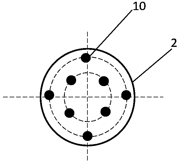
[0027] Such as figure 1 , a double-injection molten iron desulfurization device, including a desulfurization car and a molten iron tank 2 located above the desulfurization car; also includes a lifting stirring injection device. Described stirring injection device is positioned at the top of molten iron tank 2, comprises vertical stirring shaft 3 and the stirring blade 4 that is positioned at the lower end of stirring shaft 3; up and down between.

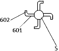
[0028] Such as image 3 , the agitating injection device also includes an air inlet pipe 5 and a plurality of horizontal L-shaped nozzles 6 . The stirring shaft 3 is provided with a cavity along the axial direction; the air inlet pipe 5 is inserted into the cavity of the stirring shaft 3 . The plurality of L-shaped nozzles 6 are symmetrically arranged on the outer periphery of the inlet pipe 5 along the center of the inlet pipe 5 , and are all located below the stirring blades 5 .

[0029] Each of the L-shaped nozzles 6 includes...


PUM


Abstract

The invention provides a double-blowing molten iron desulfurization device. The device comprises a molten iron tank and a liftable stirring jetting device, wherein the stirring jetting device comprises a vertical stirring shaft and stirring blades located at the lower end of the stirring shaft; the stirring jetting device further comprises an air intake pipe and a plurality of horizontal L-shapednozzles; the stirring shaft is axially provided with a cavity, and the air intake pipe is embedded into the cavity of the stirring shaft; the plurality of L-shaped nozzles are symmetrically arranged on the periphery of the air intake pipe along the center of the air intake pipe and are all located below the stirring blades; the bottom of the molten iron tank is provided with an annular gasket; thebottom of the molten iron tank is provided with a plurality of air ventilation bricks, wherein each air ventilation brick is connected with a blowing pipe; and a support and a plurality of flow baffle rods are arranged above the molten iron tank, wherein the upper ends of the plurality of flow baffle rods are fixed on the support, and the lower ends are inserted into the molten iron tank and close to the inner wall of the molten iron tank. According to the double-blowing molten iron desulfurization device, the contact time between a desulfurizing agent and molten iron is long, the flow fielddynamics in the blowing process of the molten iron tank is optimized, the using efficiency of the desulfurizing agent is improved, the desulfurization efficiency is high, and the equipment structure is compact.

Description

technical field [0001] The invention relates to the technical field of molten iron treatment, in particular to a double-injection molten iron desulfurization device. Background technique [0002] Hot metal desulfurization equipment includes KR mechanical stirring equipment and injection desulfurization equipment. [0003] KR mechanical stirring is to put the cross-shaped stirring head poured with refractory material and baked into the molten iron ladle to a certain depth, and the vortex generated by its rotation, the weighed desulfurizer is added to the surface of the molten iron by the feeder, and is The vortex is involved in the molten iron to make the calcium oxide-based desulfurization powder fully contact and react with the molten iron to achieve the purpose of desulfurization. Its advantage is that the dynamic conditions are superior, it is beneficial to use cheap desulfurizers such as CaO, the desulfurization effect is relatively stable, the efficiency is high (desul...

Claims


Application Information

Patent Timeline
IPC IPC(8): C21C7/064
CPCC21C7/0645
Inventor 赵慧江
Owner ZHANGJIAGANG YANGTZE RIVER COLD ROLLED PLATE CO LTD
Why Eureka
Try Eureka