
Novel hot die forging press

A hot die forging press, a new type of technology, applied in the driving device of the forging press, the forging/pressing/hammering machinery, the forging/pressing/hammer device, etc. It can improve the stability and safety, improve the accuracy and reliability, and enhance the clutch effect.

Pending Publication Date: 2020-08-25
嵊州市力博锻压机械有限公司
View PDF0 Cites 1 Cited by
  • Summary
  • Abstract
  • Description
  • Claims
  • Application Information

AI Technical Summary

Problems solved by technology

[0003] Most traditional hot die forging presses use hydraulic pumps combined with ejector rods to eject materials. Due to long-term forging, the service life of hydraulic pumps will be greatly reduced, and the surface of the forging press has almost no plasticity due to the deformation of the material during work. The oxide shell will then be broken into scale fragments, which will enter the hydraulic pump and affect the normal operation of the hydraulic pump, reducing production efficiency
Existing forging presses generally include a main motor mechanism, a clutch mechanism, an upper material ejector mechanism, and a lower material ejector mechanism. Due to the structural limitations of each mechanism, such as the clutch mechanism: the clutch brake is the core of improving the quality and production efficiency of press processed parts. The key components of the friction clutch in the prior art are complicated in structure, unstable in use performance, and poor in clutch effect, which has a great impact on the stability and safety of the press; for example, the lifting mechanism does not have a protection device and a reset device, so that the lifting action is not enough Stable; another example is that the overall volume effect of the mold height adjustment mechanism is large, which leads to the smooth operation of the slider, which makes the operation of the whole machine not stable enough. During operation, the degree of danger is high, so it does not meet the existing needs

Method used


Image

  • Novel hot die forging press
  • Novel hot die forging press
  • Novel hot die forging press

Examples


Embodiment Construction

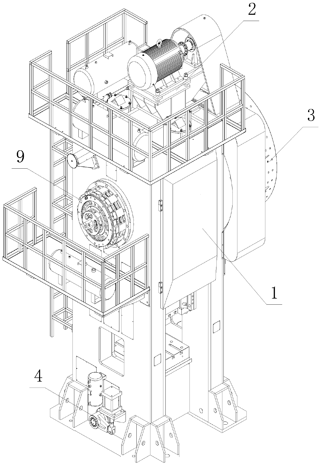
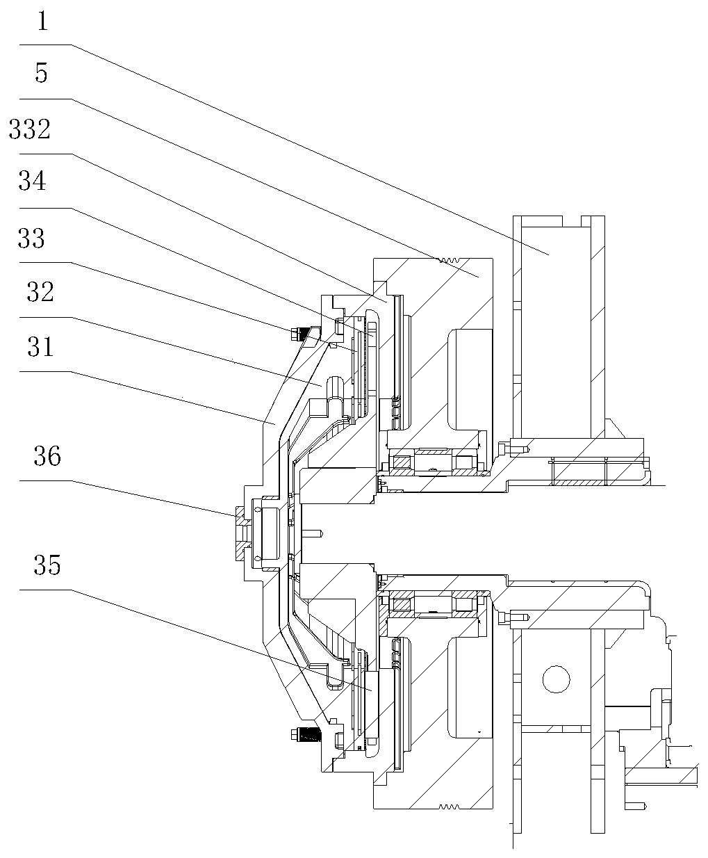
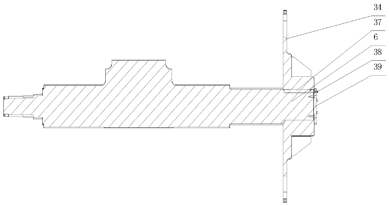
[0028] refer to Figure 1 to Figure 10, the present invention comprises a frame 1 and a main motor mechanism 2, a clutch mechanism 3, an upper material jacking mechanism and a lower material jacking mechanism 4 arranged on the frame 1, and the main motor mechanism 2 is driven and connected with a flywheel 5 through a transmission belt, so that Described flywheel 5 is connected with crankshaft 6 through clutch mechanism 3, and described crankshaft 6 is connected with connecting rod 7, and described connecting rod 7 is connected with slide block 8, and described crankshaft 6 is rotated and can make described slide block by the transmission of connecting rod 7. 8 moves up and down, the slider 8 is connected with the feeding and ejecting mechanism, the frame 1 is provided with a mold height adjustment mechanism that drives the slider 8 to rise and fall relative to the connecting rod 7, the flywheel 5 and the clutch mechanism 3 Installed on one end of the crankshaft 6, the other en...


PUM


Abstract

The invention discloses a novel hot die forging press, and relates to the technical field of hot die forging equipment. The novel hot die forging press comprises a rack, and further comprises a main motor mechanism, a clutch mechanism, an upper material ejection mechanism and a lower material ejection mechanism which are arranged on the rack, a die height adjusting mechanism for driving a slidingblock to ascend and descend relative to a connecting rod is arranged on the rack, a flywheel and a clutch are installed at one end of a crankshaft, the other end of the crankshaft is provided with a brake, and the brake is connected with a transmitting mechanism used for collecting working signals. Compared with the prior art, the clutch mechanism is innovatively designed to enable the flywheel todrive the crankshaft to move through the pneumatic effect, flywheel energy is transmitted to the crankshaft, the clutch effect is enhanced, stability and safety of the press are improved, power is provided by the motor in the die height adjusting mechanism to complete die height adjustment so as to adapt to machining of different workpieces, meanwhile, double protection of a decoder is achieved in the transmitting mechanism, and the advantage of being convenient to maintain is achieved.

Description

【Technical field】 [0001] The invention relates to the technical field of hot die forging equipment, in particular to a novel hot die forging press. 【Background technique】 [0002] The hot die forging press is a series of products produced by introducing the world's advanced technology. The hot die forging press is used in the manufacturing industries of automobiles, tractors, internal combustion engines, ships, aviation, mining machinery, petroleum machinery or hardware tools. Forging presses include plate rolling machines, shearing machines, punching machines, presses, hydraulic presses, hydraulic presses, bending machines, etc. Metal blanks pass through two relatively rotating fan-shaped dies to produce plastic deformation to form workpieces. Forging method, it is a forming A special form of rolling (longitudinal rolling), so it is widely used in modern forging production, and it is an indispensable high-precision forging equipment for modern forging production. [0003] ...

Claims


Application Information

Patent Timeline
Patent Type & Authority Applications(China)
IPC IPC(8): B21J9/18B21J13/08B21J13/14
CPCB21J9/18B21J13/085B21J13/14
Inventor 袁磊费赛波
Owner 嵊州市力博锻压机械有限公司
Learn More