3D printed curved surface conformal antenna liquid-cooling cold plate structure

A 3D printing, conformal antenna technology, applied in the direction of antenna, antenna parts, process efficiency improvement, etc., can solve the problems of difficult to remove the flow channel, difficult to form, surface pits, etc., to achieve high heat dissipation efficiency and high heat dissipation efficiency Effect

Inactive Publication Date: 2020-08-21
10TH RES INST OF CETC
View PDF9 Cites 2 Cited by
  • Summary
  • Abstract
  • Description
  • Claims
  • Application Information

AI Technical Summary

Problems solved by technology

For the forming of micro-channel cold plates with complex topological structures, there are still problems such as channel blockage, surface pits and warpage.
The minimum channel width of the aluminum alloy microchannel liquid-cooled cold plate channel formed by 3D printing technology can reach 0.5mm. If the channel width is smaller than this channel width, the alloy powder will be difficult to remove and cause channel blockage.
3D printing formed metal parts have the risk of sinking and collapsing in the unsupported forming of the suspended structure. According to the design rules of the cross-sectional structure of the flow channel, for example, when the cross-sectional structure is "□", it will be difficult to form in a specific direction by 3D printing. Set support structure, but the support structure remaining inside the runner will not be removed

Method used


Image

  • 3D printed curved surface conformal antenna liquid-cooling cold plate structure
  • 3D printed curved surface conformal antenna liquid-cooling cold plate structure
  • 3D printed curved surface conformal antenna liquid-cooling cold plate structure

Examples


Embodiment Construction

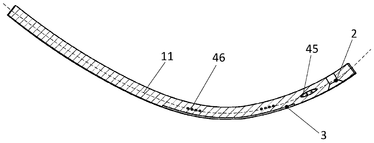
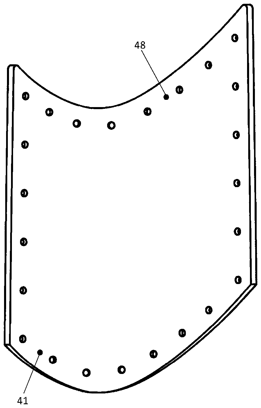
[0015] refer to Figure 1-Figure 4 . In the preferred embodiment described below, a 3D printed curved surface conformal antenna liquid-cooled cold plate structure includes: a liquid inlet 41 and a liquid outlet 48 respectively located at the lower right corner and upper left corner of the cold plate base 1, and The cold plate substrate 1 with a conformal curved surface structure and the installation hole, and the inner flow channel 4 communicating with the liquid inlet 41 and the liquid outlet 48 are kept between the antenna installation positions. The center line of the inner flow channel 4 is located on the middle curved surface 11 in the thickness direction of the cold plate substrate 1, and the liquid inlet 41 and the liquid outlet 48 are connected along the liquid inlet flow channel 43 and the liquid outlet flow channel 47 respectively. 43 and the terminal end of the outlet flow channel 47 form the inner flow channel 4 with a tapered structure; according to the design ru...


PUM

PropertyMeasurementUnit
particle size (mesh)aaaaaaaaaa

Abstract

The invention discloses a 3D printed curved surface conformal antenna liquid cooling cold plate structure, and aims to provide a liquid cooling cold plate with high curved surface conformal heat dissipation efficiency and high integral forming quality. According to the technical scheme, the center line of an inner flow channel is located on a halving curved surface in the thickness direction of acold plate base body; a liquid inlet and a liquid outlet communicate with each other along a liquid inlet flow channel and a liquid outlet flow channel correspondingly; the inner flow channel with a conical structure is formed at the termination end of the liquid inlet flow channel and the termination end of the liquid outlet flow channel; the cross section structure of a cold plate flow channel is designed into an oval main flow channel and a plurality of round micro flow channels by combining the overall structure characteristics of the cold plate and utilizing three-dimensional software; and selective laser melting 3D printing powder bed equipment is adopted, laser power is set to be 200-400 W, a laser scanning speed is set to be 1-5 m/s, high-energy laser beams are used for melting thin-layer powder laid on a powder bed in advance, and a 3D printing micro-channel cold plate is formed through layer-by-layer powder laying and layer-by-layer melting stacking, so that integrated forming from a three-dimensional die shape to a real object is achieved.

Description

technical field [0001] The invention relates to liquid cooling and heat dissipation technology, in particular to a liquid-cooled cold plate structure for a curved surface conformal antenna using 3D printing technology. Background technique [0002] The design and manufacture of antenna systems are developing in the direction of structural and functional integration, conformalization, lightweight, and miniaturization. There are more and more requirements for antenna installation on special curved surface positions, and the specifications of antenna array elements continue to expand, which puts forward higher manufacturing requirements for the size, strength, and heat dissipation capacity of antenna cold plates. Micro-channel liquid cooling heat dissipation technology is a hot spot in the thermal design of electronic equipment in recent years, and it has been gradually used in the heat dissipation of high heat flux electronic equipment. With the continuous update and transfor...

Claims


Application Information

Patent Timeline
Patent Type & Authority Applications(China)
IPC IPC(8): H01Q1/00B22F3/105B22F5/10C22C21/02B33Y10/00B33Y70/00B33Y80/00
CPCH01Q1/02B22F5/10C22C21/02B33Y10/00B33Y70/00B33Y80/00B22F10/00B22F10/28B22F10/36Y02P10/25
Inventor 雷涛刘秀利苑博张克非
Owner 10TH RES INST OF CETC
Why Eureka
Try Eureka