
Unpowered sand suction device and method

A power and gravity technology, applied in the field of unpowered sand suction devices, can solve the problems of the decline of the water storage capacity of the reservoir, the influence of the use capacity of the reservoir, and the reduction of the water storage capacity, so as to reduce the waste of water resources, reduce the sand suction efficiency and save labor and operation. handy effect

Pending Publication Date: 2020-08-11
胡波
View PDF0 Cites 2 Cited by
  • Summary
  • Abstract
  • Description
  • Claims
  • Application Information

AI Technical Summary

Problems solved by technology

[0004] In order to solve the problem of reducing the water storage capacity caused by excessive sediment in the existing reservoir and affecting the use capacity of the reservoir, the invention provides a non-powered sand suction device and method
The device uses the principle of siphon to discharge the sediment in the reservoir through the siphon through the siphon, and solves the technical problem of the long-term deposition of silt at the bottom of the reservoir, which leads to the decrease of the water storage capacity of the reservoir and the risk of dam failure of the reservoir.

Method used


Image

  • Unpowered sand suction device and method
  • Unpowered sand suction device and method

Examples


Embodiment Construction

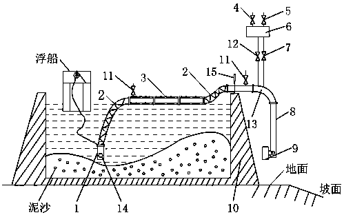
[0022] As shown in the figure, a non-powered sand suction device includes a polyurethane insulation pipe 3 , a water storage tank 6 and a siphon elbow 13 . The polyurethane insulation pipe 3 floats on the water surface, one end is connected with the vertical gravity suction head 1 through the metal hose 2, and the other end is connected with the siphon elbow 13 through the metal hose 2.

[0023] The upper end of the siphon elbow 13 is connected to the water storage tank 6 through a water inlet pipe 12 with a valve and a ventilation pipe 7 with a valve. The other side of the siphon elbow 13 is connected to the power generation pipe 8 through a flange; the bottom end of the power generation pipe 8 is connected to the siphon start valve 9 with a fixed shaft.

[0024] Diving goggles 14 are installed at the bottom of the vertical gravity suction head 1 .

[0025] The polyurethane insulation pipe 3 is provided with a vent valve 11 .

[0026] The siphon elbow 13 is provided with a ...


PUM


Abstract

The invention provides an unpowered sand suction device and method. The unpowered sand suction method is characterized in that a water storage tank is filled with water, all valves are closed, a vertical gravity suction head is underwater, a water adding valve and an air outlet valve are opened, water is injected into a siphon, and after water enters a siphon starting valve and the water level ofthe outlet end of a power generation pipe reaches a certain height, water at the inlet end of the vertical gravity suction head starts to flow to the outlet end of the power generation pipe; and the siphon starting valve gradually rises from the bottom of the original power generation pipe to one side to be fully opened along with the increase of the flow of a valve port of the siphon starting valve, and a siphon pipeline is formally started. According to the method, silt in a reservoir is discharged out of the reservoir in time through the sand suction pipe, the length of the power generationpipe can be manually set according to the actual situation on site and needs, the whole sand suction process is free of power consumption and valve resistance, impurities smaller than the pipe diameter can pass through the sand suction pipe, the sand suction efficiency is high, labor and time are saved, operation is convenient, and safety, environment friendliness and energy saving are achieved.The unpowered sand suction device and the unpowered sand suction method are suitable for use.

Description

technical field [0001] The invention relates to the field of dredging and sand discharge of reservoirs, in particular to a non-powered sand suction device and method. Background technique [0002] In the process of people's production and life, water is a kind of non-renewable material resource that human beings rely on for survival, and the reservoir is a large container to ensure that water resources will not be lost. When the height of the dam is fixed, its effective The volume will directly affect the water storage capacity and actual use capacity of the reservoir, and the regular dredging and sand discharge of the reservoir will directly affect the effective volume of the reservoir. Reservoirs are generally located near the downstream between two mountains or mountains. The rainwater that falls from the sky every summer is naturally collected into the reservoir through the potential difference between the mountain, the ditch and the ground. Similarly, the sediment betw...

Claims


Application Information

Patent Timeline
Patent Type & Authority Applications(China)
IPC IPC(8): E02F5/28E02F3/88E02F3/90E02F3/92E02F7/10
CPCE02F3/88E02F3/90E02F3/92E02F3/9243E02F5/28E02F7/10
Inventor 胡波胡立文
Owner 胡波
Learn More