Ultra-low emission method and device for sulfur recovery tail gas

A sulfur recovery tail gas and sulfur recovery technology, applied in separation methods, chemical instruments and methods, gas treatment, etc., can solve the problems of high cost, complicated process, secondary pollution, etc., and achieve extended life, simple equipment, and reduced corrosion Effect

Inactive Publication Date: 2020-08-04
YANKUANG GRP CO LTD +1
View PDF5 Cites 0 Cited by
  • Summary
  • Abstract
  • Description
  • Claims
  • Application Information

AI Technical Summary

Problems solved by technology

[0005] The present invention provides a method and device for ultra-low discharge of sulfur recovery tail gas, which overcomes the deficiencies of the above-mentioned prior art, and can effectively solve the problems of high cost, complex process and secondary production in the process of sulfur recovery and treatment. secondary pollution problem

Method used


Image

  • Ultra-low emission method and device for sulfur recovery tail gas

Examples


Embodiment 1

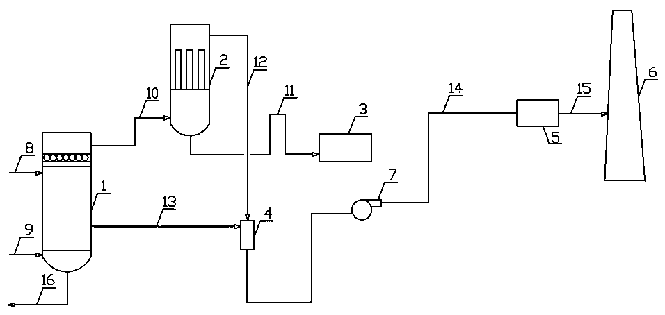
[0020] Embodiment 1: as attached figure 1 As shown, the method for the ultra-low emission of the sulfur recovery tail gas is carried out according to the following steps: the first step, the high temperature sulfur recovery mixed tail gas enters the WSA condenser 1 through the sulfuric acid process gas pipeline 9, and enters through the cold air pipeline 8 The cold air in the WSA condenser 1 undergoes heat exchange and cools down to become a low-temperature sulfur recovery mixed tail gas, and the temperature of the cold air rises to become hot air; in the second step, the low-temperature sulfur recovery mixed tail gas is discharged from the upper outlet of the WSA condenser 1, and is discharged from the first A sulfur recovery tail gas treatment pipeline 10 enters the acid mist trap 2, and the low-temperature acid mist entrained in the low-temperature sulfur recovery tail gas is further captured by the acid mist trap 2. After the hot air is discharged through the lower gas outl...

Embodiment 2

[0022] Embodiment 2: As an optimization of the above embodiment, in the low-temperature sulfur recovery mixed tail gas, the temperature of the sulfur recovery mixed tail gas is 80°C to 104°C. The sulfur content in the acid mist entrained by the low-temperature sulfur recovery mixed tail gas after the heat exchange of WSA condenser 1 can be reduced to 50mg / Nm 3 .

[0023] The high-temperature sulfuric acid-containing process gas (high-temperature sulfur recovery tail gas) fed into the condenser 1 conducts heat exchange and cooling with the cold air, which can not only enable the acid mist collector 2 to better capture the acid mist, but also make rational use of the hot air. Control the mixing ratio of the hot air and the sulfur recovery tail gas captured by the acid mist collector 2 to 2:1, so that the temperature of the sulfur recovery tail gas in the mixer 4 is 130°C to 160°C, effectively reducing the acid mist in the tail gas Condensation in the third sulfur recovery tail ...

Embodiment 3

[0024] Embodiment 3: As an optimization of the above embodiment, the sulfuric acid recovery pipeline is an inverted U-shaped pipeline. The inverted U-shaped recovery sulfuric acid pipeline can make the liquid in the pipeline quickly return to the acid intermediate storage tank 3 by utilizing the high head difference.


PUM


Abstract

The invention relates to the technical field of sulfur recovery tail gas treatment and relates to an ultra-low emission method and device for sulfur recovery tail gas. Sulfur recovery mixed tail gas enters a WSA condenser and is cooled into low-temperature sulfur recovery mixed tail gas; entrained low-temperature acid mist is further trapped in an acid mist catcher after discharging; hot air is conveyed into a mixer to be mixed with low-temperature gas-phase acid mist to form mixed gas, and liquid-phase sulfuric acid is discharged into an acid intermediate storage tank; the mixed gas is pressurized by a tail gas fan, then enters a dry desulfurization, denitrification and dust removal integrated device to be subjected to desulfurization, denitrification and dust removal, and is discharged through a sulfur recovery chimney after reaching the ultralow emission standard. The acid mist in the sulfur recovery tail gas is captured and then transported to the integrated dry desulfurization, denitrification and dust removal device for treatment; the method is fast and convenient, the equipment is simple, the corrosion of the acid mist to equipment pipelines is reduced, the service life of the equipment pipelines is prolonged, sulfuric acid is recycled, the reutilization of waste gas resources is realized, meanwhile, the index of ultralow emission of tail gas is achieved, and the environmental protection requirement is met.

Description

technical field [0001] The invention relates to the technical field of sulfur recovery tail gas treatment, and relates to a method and device for ultra-low emission of sulfur recovery tail gas. Background technique [0002] Sulfur recovery units in coal chemical enterprises generally adopt Topsoe’s wet-process sulfuric acid production technology in Denmark, and the tail gas emission index in the original design is SO 2 ≤960mg / m 3 , sent to a 60-meter chimney for local discharge. During actual operation, SO in the tail gas discharged by the sulfur recovery device 2 The measured value is generally 200mg / m 3 up to 600mg / m 3 between. On April 16, 2015, the Ministry of Environmental Protection announced the GB31571-2015 "Petrochemical Industry Pollutant Discharge Standard" (hereinafter referred to as the "Standard"). Existing enterprises will implement SO from July 1, 2017 2 The limit is 100mg / m 3 emission indicators. The actual operating emission index exceeds the requir...

Claims


Application Information

Patent Timeline
IPC IPC(8): B01D46/00B01D53/00C01B17/90
CPCB01D46/00B01D53/002B01D2257/302C01B17/90
Inventor 吴章姚刚孙清涛齐兆焜于德玲孙友文孙岩韩强杨凤英石勇李家栋张路强常淑华高吉文张永军张忠喜王玉伟张腾飞
Owner YANKUANG GRP CO LTD
Why Eureka
Try Eureka