Eureka AIR delivers breakthrough ideas for toughest innovation challenges, trusted by R&D personnel around the world.

Feed network and antenna feed system

A feeding network and antenna feeding technology, which is applied to antennas, antenna parts, antenna supports/installation devices, etc., can solve the problems of different line widths, complex designs, and excessive bending of the feeding network, and achieve The effect of high consistency and reliability, simplified design, and reduced number of segments and bends

Pending Publication Date: 2020-07-31
ANHUI TATFOOK TECH CO LTD
View PDF0 Cites 0 Cited by
  • Summary
  • Abstract
  • Description
  • Claims
  • Application Information

AI Technical Summary

Problems solved by technology

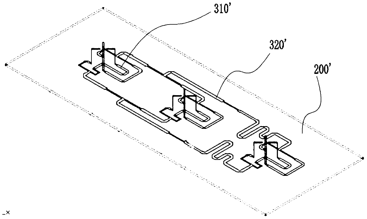
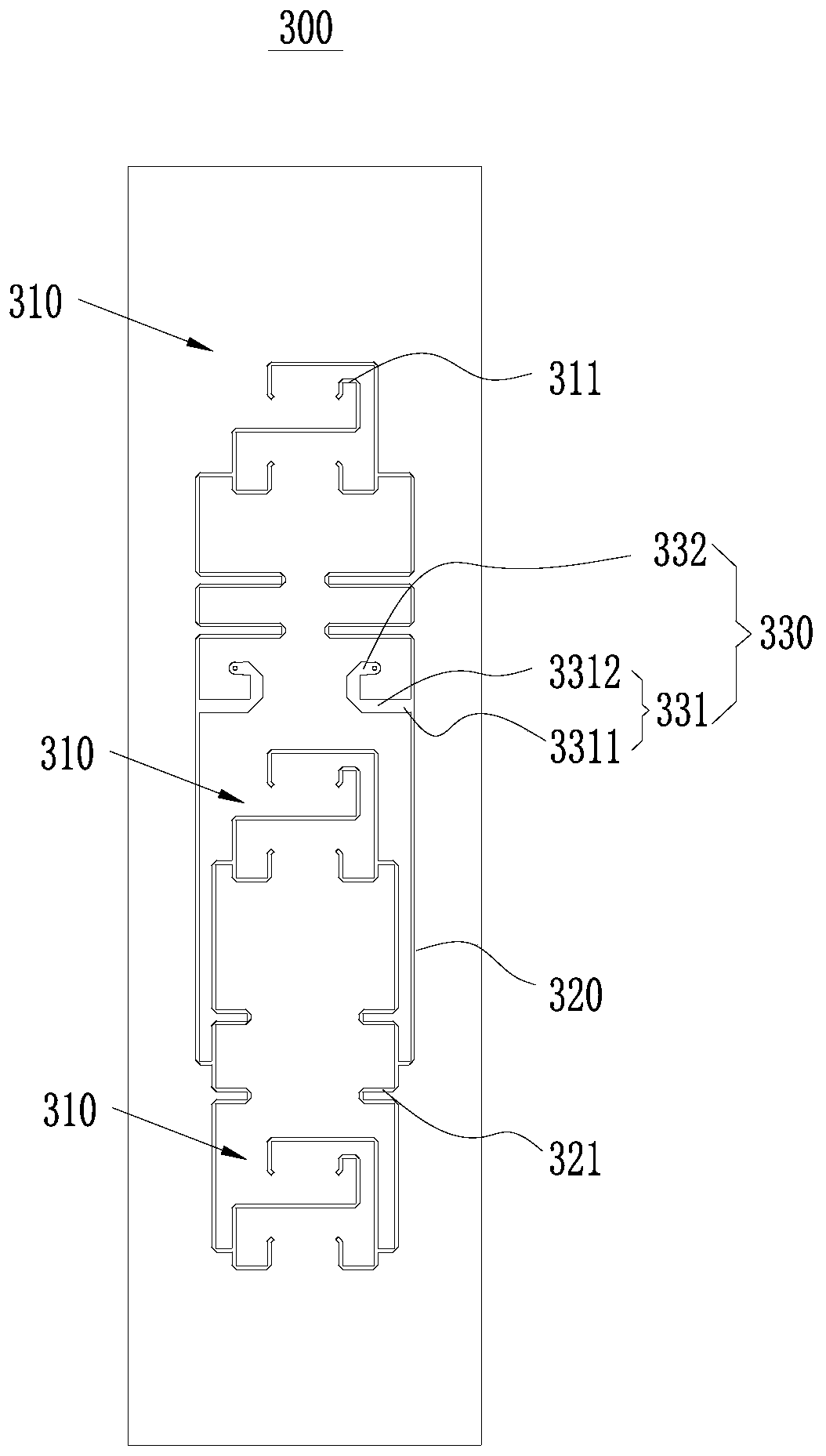
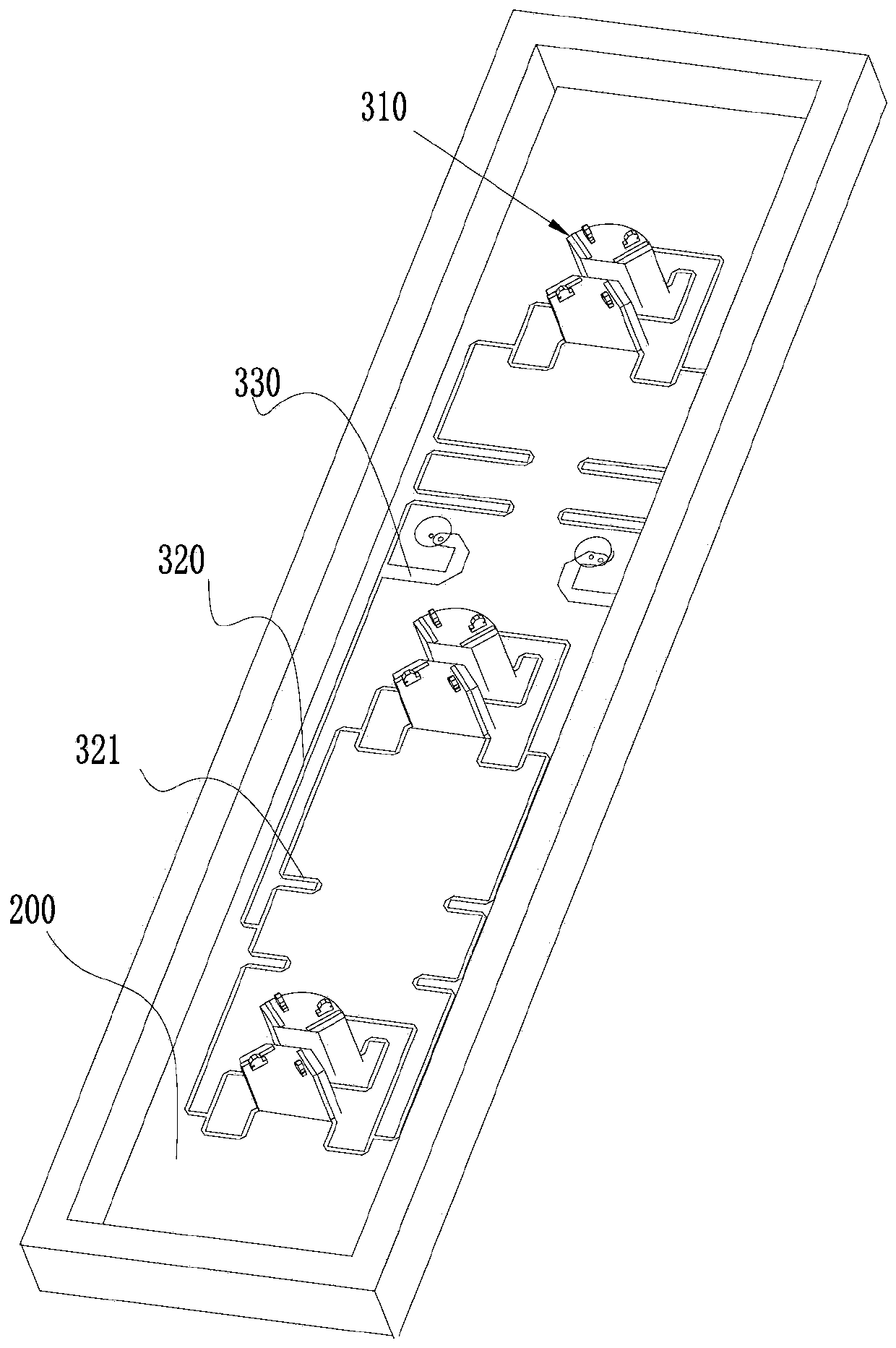
[0006] The purpose of the present invention is to provide a feeding network and an antenna feeding system to solve the technical problems in the prior art that the line width of each stage of the feeding network is inconsistent, resulting in complex design, excessive bending, and large loss

Method used


Image

  • Feed network and antenna feed system
  • Feed network and antenna feed system
  • Feed network and antenna feed system

Examples


Embodiment Construction

[0028] The technical solutions of the present invention will be clearly and completely described below in conjunction with the accompanying drawings. Apparently, the described embodiments are some of the embodiments of the present invention, but not all of them. Based on the embodiments of the present invention, all other embodiments obtained by persons of ordinary skill in the art without making creative efforts belong to the protection scope of the present invention.

[0029] In the description of the present invention, it should be noted that the terms "center", "upper", "lower", "left", "right", "vertical", "horizontal", "inner", "outer" etc. The indicated orientation or positional relationship is based on the orientation or positional relationship shown in the drawings, and is only for the convenience of describing the present invention and simplifying the description, rather than indicating or implying that the referred device or element must have a specific orientation, ...


PUM


Abstract

The invention provides a feed network and an antenna feed system. The antenna feed system comprises a feed plate, arrays and a feed network, wherein the feed network comprises array matching lines, sub-array matching lines and debugging lines, the line width of the array matching line is equal to the line width of the sub-array matching line, the line width of the debugging line can be unequal tothe line width of the array matching line and the line width of the sub-array matching line, the array matching line is used for being connected with the array, the adjacent arrays are connected through the sub-array matching line, the debugging lines are arranged on the sub-array matching lines, and the input impedance of a feeder line is adjusted and matched through the length and the width of the debugging line. According to the design method that the line width of the array matching line and the line width of the sub-array matching line are equal, the design of a matching circuit is greatly simplified, the number of sections and the number of bends of the matching lines are reduced, and losses are reduced; and high consistency and reliability can be achieved when an electroplating process is adopted for machining while the whole circuit diagram is attractive and simple.

Description

technical field [0001] The present invention relates to the technical field of 5G wireless communication base stations, in particular to a feeding network and an antenna feeding system. Background technique [0002] The feed network is an important component of the base station antenna. It connects the antenna port and the array element to form a path for radio frequency signal transmission, and realizes functions such as impedance matching and amplitude phase distribution. [0003] The feed network is closely related to the performance of the antenna array, and directly affects the parameters such as the standing wave ratio, radiation efficiency, beam pointing, sidelobe level, and zero point of the antenna array. In the feed network design of the base station antenna network, focus on the impedance matching, insertion loss, amplitude and phase distribution and other characteristics of the feed network to reduce antenna array loss, improve radiation efficiency, increase ante...

Claims


Application Information

Patent Timeline
Patent Type & Authority Applications(China)
IPC IPC(8): H01Q1/24H01Q1/50H01Q1/36
CPCH01Q1/246H01Q1/36H01Q1/50
Inventor 靳炉魁丁庆龙
Owner ANHUI TATFOOK TECH CO LTD
Why Eureka
Eureka Blog
Learn More