
Top-blowing powder spraying method for electric furnace smelting

An electric furnace smelting and top blowing technology, applied in the direction of electric furnaces, furnaces, furnace types, etc., can solve problems such as uneven mixing in the full flow field, tight combination of spray guns and furnace walls, deformation and bending of obliquely inserted gun rods, and reach the installation limit of the furnace top. High requirements are low, improving the effect of smelting and improving the refining rate

Inactive Publication Date: 2020-07-31
成都亿兆晶创科技有限公司
View PDF10 Cites 0 Cited by
  • Summary
  • Abstract
  • Description
  • Claims
  • Application Information

AI Technical Summary

Problems solved by technology

Many problems have been exposed during the use of this mechanism. For example, the tight combination of the spray gun and the furnace wall cannot be achieved, and cracks occur, resulting in leakage of molten metal or molten slag, resulting in safety accidents; the burnout of the spray gun cannot be compensated, and the service life is short.
[0004] In addition, some manufacturers use obliquely inserted spray guns on the top of the furnace, but the cantilever of the spray gun must be very long, and the installation takes up a large space. Generally, it will be mechanically interfered by the furnace top, and most of them cannot form a complete application plan; and the inclined angle is small, generally It cannot meet the requirements of the process on the angle; in addition, under the influence of high temperature, the obliquely inserted gun shaft is easily deformed and bent, and cannot be plugged and replaced; and the spray point is fixed, so dynamic spray scanning cannot be realized. The blind area is particularly large, and the mixing of the entire flow field is uneven. Poor metallurgy

Method used


Image

  • Top-blowing powder spraying method for electric furnace smelting
  • Top-blowing powder spraying method for electric furnace smelting
  • Top-blowing powder spraying method for electric furnace smelting

Examples


Embodiment Construction

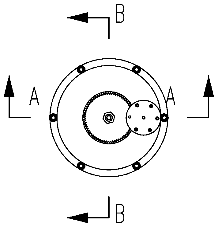
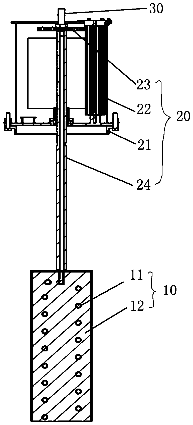
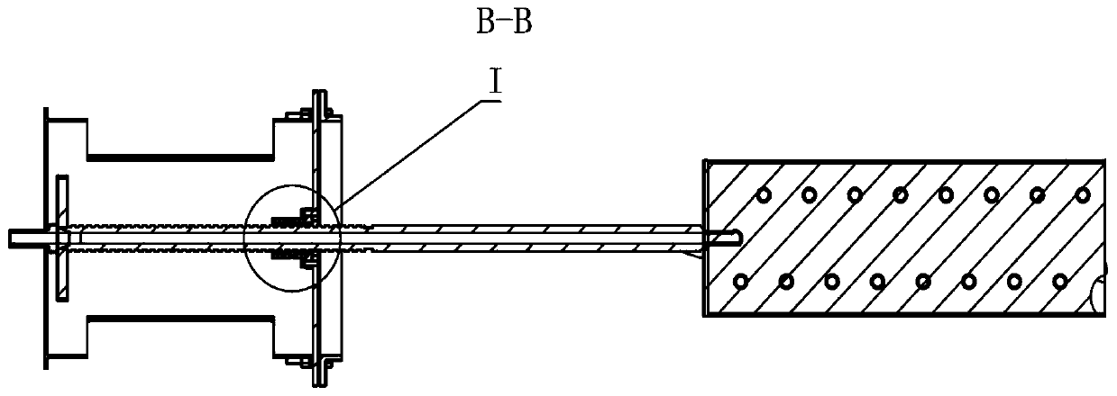
[0024] Hereinafter, the top blowing powder injection method for electric furnace smelting of the present invention will be described in detail with reference to exemplary embodiments. It should be understood that, in the present invention, the terms "upper end" and "lower end", "upper end" and "lower end" are for the convenience of describing the relative structural relationship of different components, rather than strict positional restrictions, for example, when When the telescopic rotary joint in the present invention is laid flat in the non-installed state, the "upper end" and "lower end", "upper end" and "lower end" can also be referred to as "left end" and "right end", " Left End” and “Right End”. In addition, the terms "first", "second", and "third" are only used to distinguish different components, and are not strictly limited to the order.

[0025] In order to more clearly and completely describe an exemplary embodiment of the method for top-blown powder injection in...


PUM


Abstract

The invention provides a top-blowing powder spraying method for electric furnace smelting. The method comprises the following steps that air powder is blown into a furnace by adopting one or more thantwo top-blowing powder spraying systems which are uniformly distributed on a furnace cover; one or more than two top-blowing powder spraying systems can be controlled independently or in a linkage manner; and when any top-blowing powder spraying system is controlled, the method can drive a lifting mechanism through a driving unit in any top-blowing powder spraying system so as to drive a spiral spraying pipe of a lifting spiral spraying gun to rotate and lift, and therefore air powder is sprayed into the furnace at a constant spiral lift angle, wherein the system comprises a liftable spiral spray gun, a lifting mechanism, a driving unit, a stretchable rotary joint and a gas powder supply device. According to the method, multi-point powder spraying can be achieved, each top-blowing powderspraying system can operate independently and can also operate in a linkage mode, and the smelting effect of the electric furnace can be improved; the blowing angle can be kept unchanged for a long time; and the equipment is light in weight and low in furnace top mounting height limit requirement.

Description

technical field [0001] The invention relates to the technical field of electric furnace metallurgy, in particular to a top-blown powder spraying method for electric furnace smelting, which can spray powder-containing airflow into molten metal during a specific smelting task period to uniformly spray powder into the molten pool And / or slag control, so as to create good reaction kinetic conditions for smelting, which is conducive to strengthening the metallurgical process and improving the smelting effect. Background technique [0002] Generally, the process of electric furnace smelting is a chemical reaction process of various elements, and the full contact between elements directly determines the smelting effect. The purpose of spraying powder into molten metal is to create good chemical reaction conditions. [0003] At present, the powder spraying device used in the electric furnace is mainly a furnace wall obliquely inserted spray gun. The spray gun is inserted obliquely i...

Claims


Application Information

Patent Timeline
IPC IPC(8): C21C5/52C21C7/00
CPCC21C5/52C21C7/0037Y02P10/20
Inventor 向志佳张辰杨飞龙飞虎唐朝虎郭文明
Owner 成都亿兆晶创科技有限公司
Learn More