System and method for monitoring and dynamically regulating and controlling flow field distribution in denitration link of coal-fired power plant

A technology for coal-fired power plants and flow field distribution, applied in separation methods, chemical instruments and methods, neural learning methods, etc., can solve problems that do not involve flow field monitoring and regulation, poor feasibility and operability, and lack of functions

Pending Publication Date: 2020-07-31
HUADIAN ELECTRIC POWER SCI INST CO LTD
View PDF8 Cites 7 Cited by
  • Summary
  • Abstract
  • Description
  • Claims
  • Application Information

AI Technical Summary

Problems solved by technology

Domestic patent "Optimization and adjustment method for SCR denitrification system of coal-fired power station based on CFD", patent number CN104474896B, using computational fluid dynamics (CFD) to analyze the flow field and NH 3 The real-time calculation of the concentration field and the guidance of the DCS to control the flow rate of ammonia injection have the advantage of making full use of advanced numerical simulation methods, but the disadvantage is that the real-time CFD calculation is not feasible and operable in actual production, and the technical level of personnel is required High, and the invention does not involve flow field monitoring and regulation
Domestic patent "system and method for determining air entrapment in ladle", patent application number 201910163165.3, proposes to use transient CFD to simulate the tapping process of liquid steel and calculate the amount of air entrapment, and the formed data set is used for training Artificial neural network, the trained artificial neural network model is used to predict the air interception under new input parameters, but its artificial neural network model is only used for result prediction, not used to guide the adjustment of production process parameters, the invention It does not aim at adjusting the technological parameters of the production process so as to optimize the production output results, nor does it have the function of this aspect, and the production field applicable to this invention is also obviously different from the present invention

Method used


Image

  • System and method for monitoring and dynamically regulating and controlling flow field distribution in denitration link of coal-fired power plant
  • System and method for monitoring and dynamically regulating and controlling flow field distribution in denitration link of coal-fired power plant
  • System and method for monitoring and dynamically regulating and controlling flow field distribution in denitration link of coal-fired power plant

Examples


Embodiment Construction

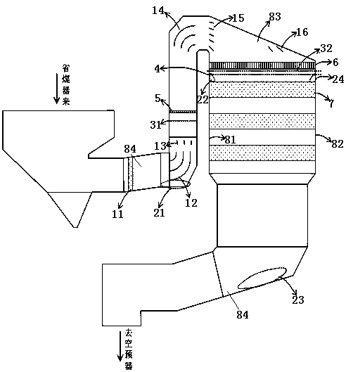
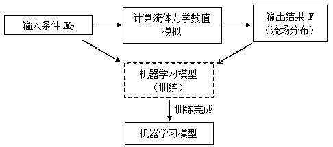
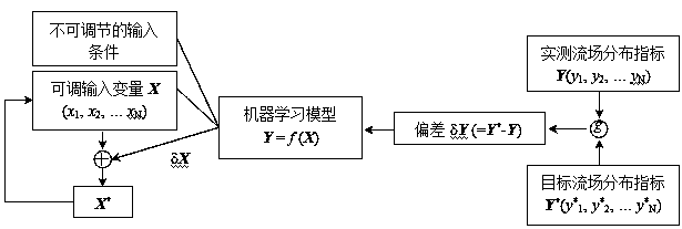
[0055] The present invention will be further described in detail below in conjunction with the accompanying drawings and examples. The following examples are explanations of the present invention and the present invention is not limited to the following examples.

[0056] Example.

[0057] see Figure 1 to Figure 3 It should be noted that the structures, proportions, sizes, etc. shown in the drawings attached to this specification are only used to match the content disclosed in the specification, for those who are familiar with this technology to understand and read, and are not used to limit the present invention Therefore, it has no technical substantive meaning, and any modification of structure, change of proportional relationship or adjustment of size shall still fall into the within the scope covered by the technical content disclosed in the present invention. At the same time, if there are terms such as "upper", "lower", "left", "right", "middle" and "one" in this spe...


PUM


Abstract

The invention relates to a system and method for monitoring and dynamically regulating and controlling flow field distribution of a denitration link of a coal-fired power plant, and belongs to the field of SCR denitration of the coal-fired power plant. The system comprises a denitration reactor and a flue, the flue is connected with the denitration reactor; the structure is characterized in that the system further comprises an ammonia spraying grid and a rectifying grid, the ammonia spraying grid is mounted in the flue; the rectifying grid is arranged in the denitration reactor; a first-layercatalyst is arranged in the denitration reactor; a first flow guide plate, a second flow guide plate, a third flow guide plate, a fourth flow guide plate, a fifth flow guide plate and a sixth flow guide plate are sequentially arranged in the flue and the denitration reactor along the flowing direction of the flue gas; wherein a first dust-easy-to-deposit area and a third dust-easy-to-deposit areaare in the flue, a second dust-easy-to-deposit area and a fourth dust-easy-to-deposit area are in the denitration reactor, a first flow velocity monitoring section is arranged in the flue, and the denitration reactor is provided with a second flow velocity monitoring section and a flow direction monitoring section.

Description

technical field [0001] The invention relates to a system and method for monitoring and dynamically regulating the flow field distribution in the denitrification link of a coal-fired power plant, belonging to the field of SCR denitrification in a coal-fired power plant. Background technique [0002] Selective Catalytic Reduction (SCR) is commonly used in coal-fired power plants to remove NOx from flue gas. After the flue gas comes out of the economizer at the rear of the furnace, it flows through the ammonia injection grid (Ammonia Injection Grid, referred to as "AIG"), and mixes with the reducing agent (such as ammonia gas) injected here, and continues to flow to the denitrification reaction device. The flue gas flows through the multi-layer catalyst in the denitrification reactor. Under the action of the catalyst, NOx and NH 3 react to form N 2 and H 2 O, to complete the denitrification reaction. The flow field distribution and its uniformity have a significant impact ...

Claims


Application Information

Patent Timeline
Patent Type & Authority Applications(China)
IPC IPC(8): B01D53/86B01D53/56G06N3/08G06N20/00
CPCB01D53/8625B01D53/346G06N3/084G06N20/00B01D2258/0283B01D2251/2062
Inventor 柳冠青马治安孙海峰彭丽潘威丞董方李宗慧张伟阔石战胜刘袖敬旭业
Owner HUADIAN ELECTRIC POWER SCI INST CO LTD
Why Eureka
Try Eureka