
Cyclone extraction device and separation system using same

An extraction device and separation system technology, which is applied in separation methods, solvent extraction, liquid solution solvent extraction, etc., can solve the problems of low extraction and mass transfer efficiency, and the inability to fully mix the organic phase and the aqueous phase, so as to improve the rotation stability , Reduce the impact of mass transfer reaction heat, and reduce costs

Active Publication Date: 2020-07-31
浙江科菲科技股份有限公司
View PDF10 Cites 0 Cited by
  • Summary
  • Abstract
  • Description
  • Claims
  • Application Information

AI Technical Summary

Problems solved by technology

[0004] However, in the prior art, the organic phase and the aqueous phase cannot be fully mixed, resulting in the problem of low extraction and mass transfer efficiency; therefore, a new solution needs to be proposed to solve this problem

Method used


Image

  • Cyclone extraction device and separation system using same
  • Cyclone extraction device and separation system using same
  • Cyclone extraction device and separation system using same

Examples


Embodiment 1

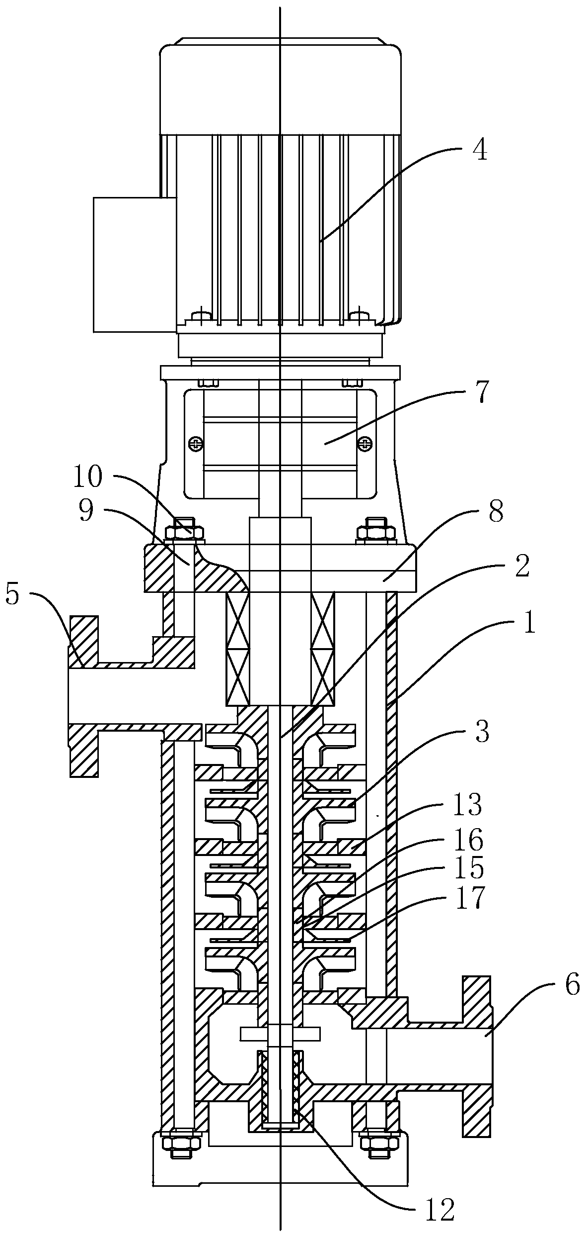
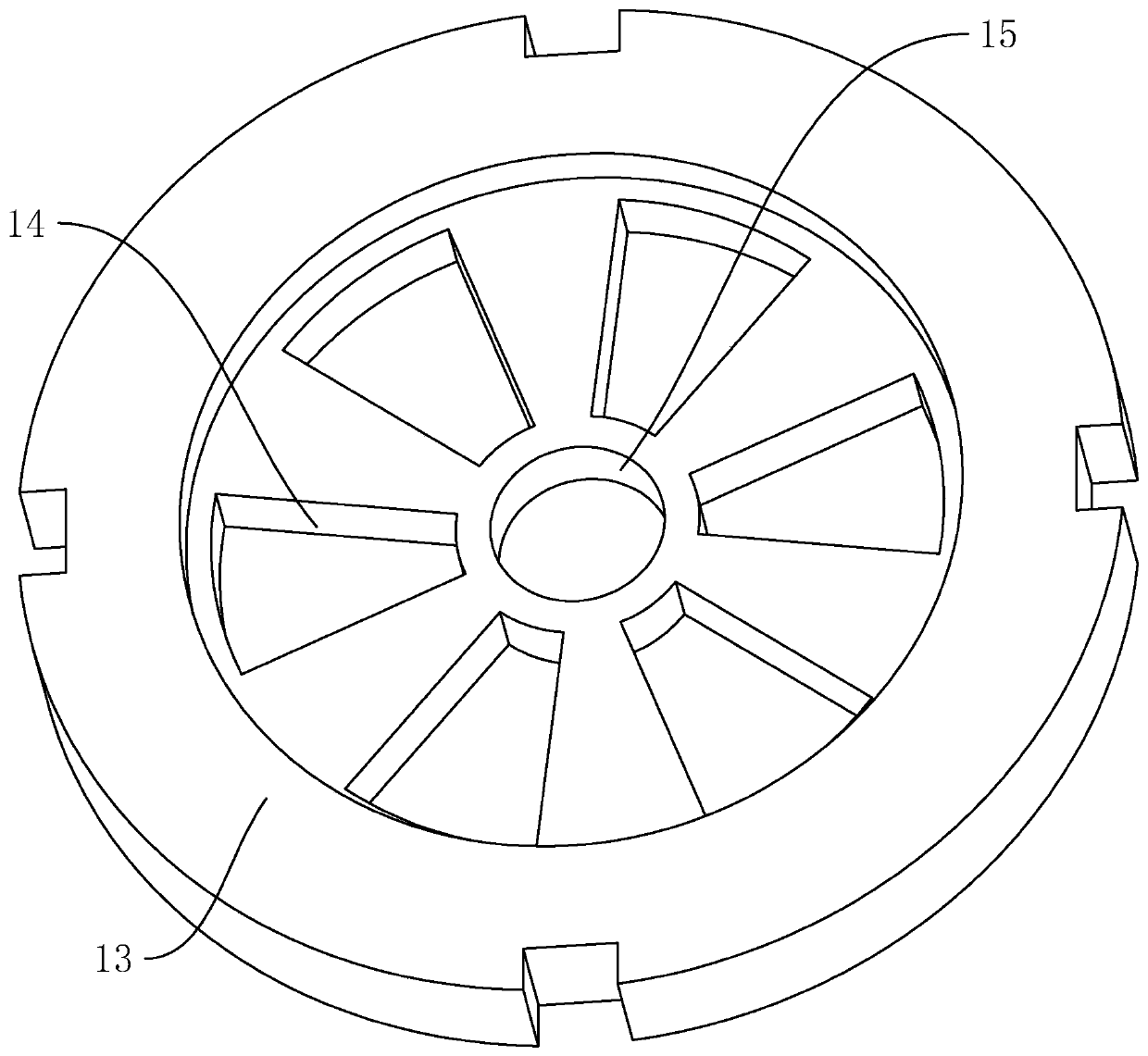
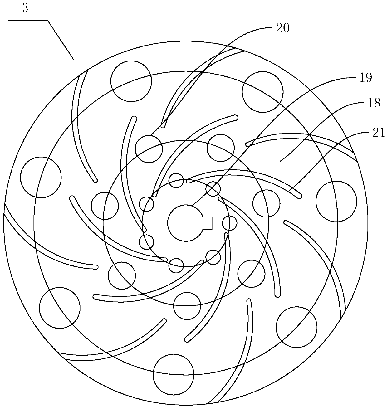
[0042] Embodiment one: cyclone extraction device, such as figure 1 As shown, it includes a cylindrical shell 1, a main shaft 2 rotatably connected along the central axis of the shell 1, a swirl reaction disc 3 coaxially fixed to the main shaft 2, and a swirl extraction motor 4 for driving the main shaft 2. The cylindrical shell 1 A liquid inlet 5 and a liquid outlet 6 are respectively integrally formed at the upper and lower ends of the outer wall of the circumference, and a connector 7 is installed between the top of the shell 1 and the swirl extraction motor 4, and the number of swirl reaction discs 3 is at least four. In the embodiment, the specific number of swirling flow reaction discs 3 is three, and they are arranged at equal intervals along the length direction of the main shaft 2 .

[0043] When the cyclone extraction device is used for extraction or stripping, the two-phase feed liquid enters the shell 1 through the liquid inlet 5, and flows from top to bottom along ...

Embodiment 2

[0049] Embodiment two: utilize the separation system of cyclone extraction device, as Figure 4 As shown, including extraction system A, extraction system B, extraction system C, extraction system D, stripping cobalt system A, stripping cobalt system B, stripping copper system A, stripping copper system B, stripping iron system A, Iron stripping system B, raw material liquid storage tank 22, organic storage tank after extraction 23, organic storage tank after copper washing 24, extraction raffinate storage tank 25, cobalt sulfate storage tank 26, reverse cobalt acid storage tank 27, after iron washing Organic storage tank 28, refined sulfuric acid tank 29, refined liquid alkali tank 30, pure water tank 31, saponification tank 32, sodium sulfate liquid tank 33, copper washing acid solution preparation tank 34, anti-cobalt acid preparation tank 35, anti-ferric zinc acid preparation Tank 36; extraction system A, extraction system B, extraction system C, extraction system D, strip...


PUM


Abstract

The invention discloses a cyclone extraction device, relates to metal melting, and aims to solve the problem that the extraction mass transfer efficiency is low. The device is characterized in that: the device comprises a cylindrical shell, a main shaft arranged along the central axis of the shell, at least four cyclone reaction discs coaxially fixed on the main shaft, and a cyclone extraction motor used for driving the main shaft, wherein a liquid inlet and a liquid outlet are formed in the upper end and the lower end of the circumferential outer wall of the cylindrical shell respectively, aconnector is arranged between the top end of the shell and the cyclone extraction motor, and the cyclone reaction discs are arranged at equal intervals in the length direction of the main shaft. The cyclone extraction device provided by the invention assists in extraction or back extraction, effectively improves the mass transfer efficiency, and effectively reduces the influence of mass transfer reaction heat.

Description

technical field [0001] The invention relates to metal smelting, more specifically, it relates to a cyclone extraction device and a metal separation system using the device. Background technique [0002] Extraction separation is an important means of metal separation in metallurgical industry production. Traditional extraction devices are mostly box-type, tower-type, column-type and other extraction forms. The most widely used box-type extraction box is mainly composed of two parts: a mixing chamber and a clarification chamber. Box extraction belongs to the step-by-step contact liquid-liquid mass transfer equipment. The mixing chamber is equipped with a stirrer, and the clarification chamber is an empty chamber with a large cavity volume, which is used for static stratification of the mixed two-phase liquid. The mixing chamber and the clarifying chamber are usually on the same plane, and the volume of the mixing chamber is relatively large. [0003] For example, a hydrometa...

Claims


Application Information

Patent Timeline
IPC IPC(8): B01D11/04C22B3/02C22B3/26C22B23/00C22B15/00C22B19/20C22B47/00C22B26/20C22B26/22
CPCB01D11/0488B01D11/0457B01D11/0434C22B3/02C22B23/04C22B15/0063C22B19/20C22B47/00C22B26/20C22B26/22C22B3/26Y02P10/20
Inventor 李想邓涛侯新常陈东达
Owner 浙江科菲科技股份有限公司
Learn More