Jet type oil injector

An oil injector and jet technology, which is used in lubricating oil control valves, machines/engines, liquid variable capacity machines, etc., can solve problems such as component tolerances and difficulty in batching, and reduce manufacturing costs and tolerances. , the effect of simplifying the orientation

Active Publication Date: 2020-04-21
德国斯凯孚润滑油系统有限责任公司
View PDF5 Cites 0 Cited by
  • Summary
  • Abstract
  • Description
  • Claims
  • Application Information

AI Technical Summary

Problems solved by technology

The reason is mainly due to the fact that due to the arrangement and installation of such injectors there are component tolerances which make it difficult to carry out small dosage quantities.

Method used


Image

  • Jet type oil injector
  • Jet type oil injector

Examples


Embodiment Construction

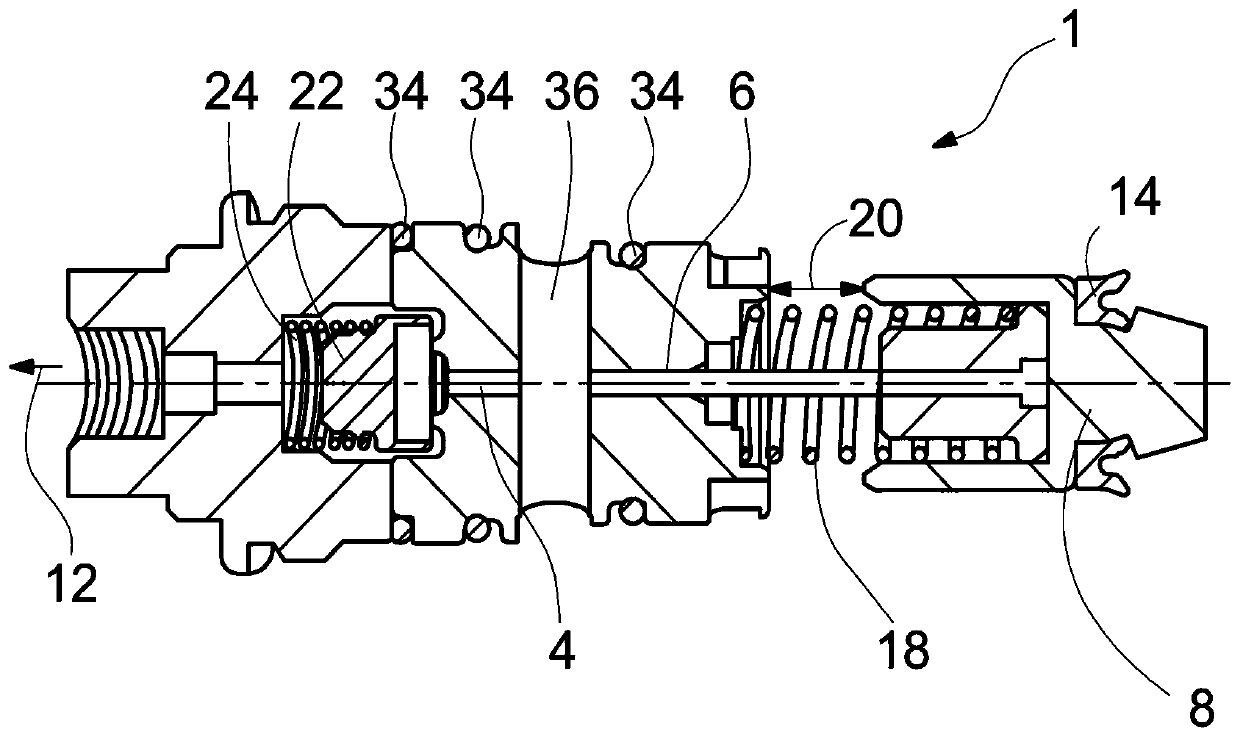
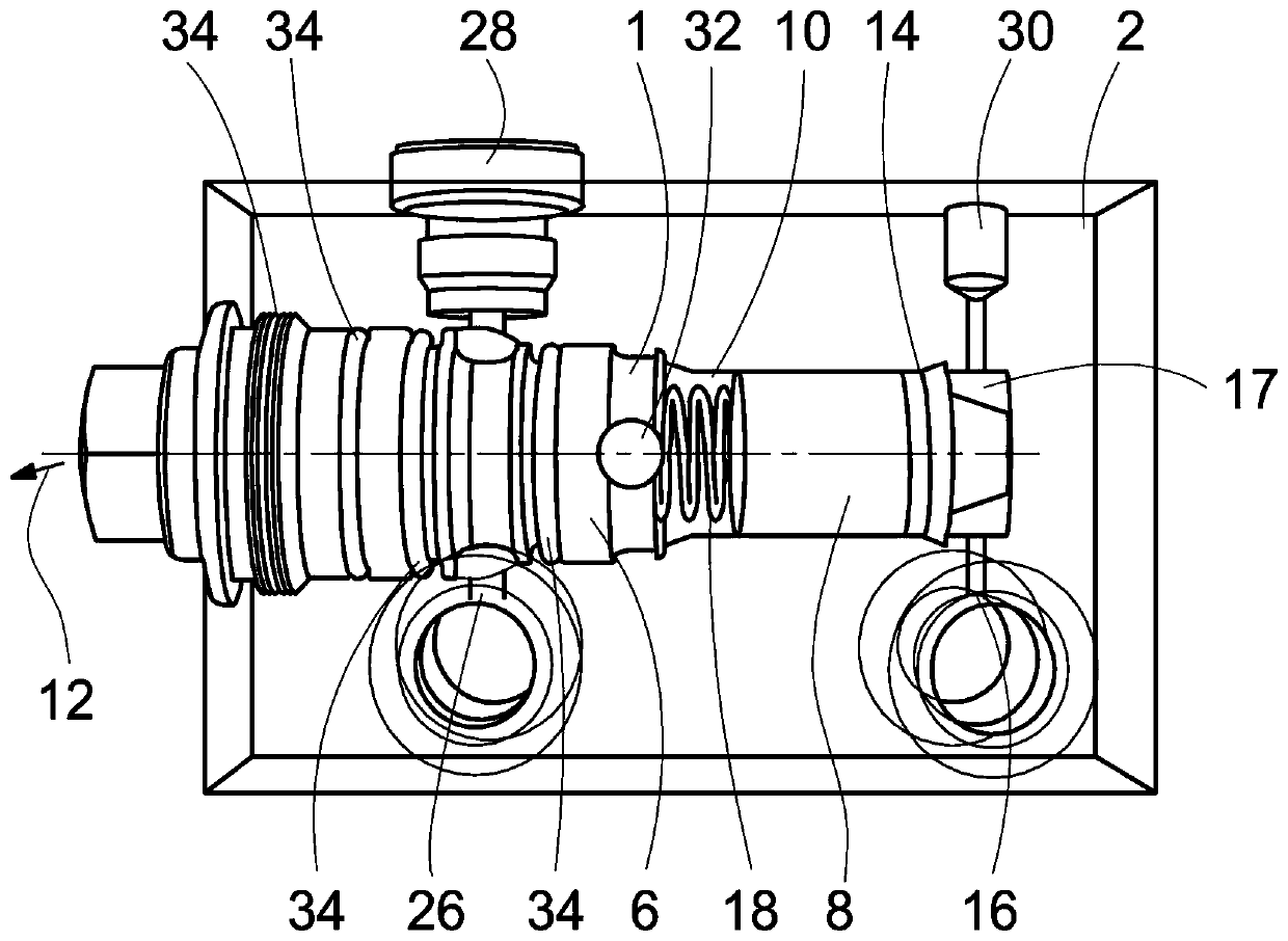
[0021] figure 1 and 2 A sectional view and a perspective view of the jet lubricator 1 , which is installed in the housing 2 , are shown. The jet lubricator 1 has a cavity 4 for containing a quantity of lubricant. The jet oiler 1 also has a dosing piston 6 and an actuating piston 8 . The cavity 4 , the dosing piston 6 and the actuating piston 8 are arranged in a stepped bore 10 in the housing 2 , which is designed as a blind bore.

[0022] During operation, the dosing piston 6 is actuated by the actuating piston 8 in order to transfer the lubricant to the lubrication points, so that the dosing piston 6 moves into the cavity 4 and thus discharges the lubricant present in the cavity 4 from the jet lubricator. The lubricant discharge direction is indicated by arrow 12 .

[0023] In the region of the actuating piston 8 , radial openings 16 are provided in the stepped bore, which can be connected to a fluid delivery unit (not shown). Through the radial openings 16 it is possibl...


PUM


Abstract

The invention relates to a jet type oil injector (1) having a cavity (4) for receiving a quantity of a lubricant, a dosing piston (6) and an actuating piston (8). The dosing piston (6) is designed todischarge the lubricant in the cavity (4) in the operating state and to release the cavity (4) for receiving the lubricant in the non-operating state. The actuating piston (8) can be controlled by a fluid and is designed to actuate the dosing piston (6). The cavity (4), the dosing piston (6) and the actuating piston (8) are arranged in a stepped bore (10), and the stepped bore (10) is designed asa blind bore.

Description

technical field [0001] The invention relates to a jet lubricator according to the preamble of claim 1 , having a cavity for receiving a quantity of lubricant. Background technique [0002] Jet lubricators are used for conveying and dosing lubricating materials. In this case, the supply of lubricating material takes place from a central container or central pipe, wherein jet lubricators are connected to the container or pipe for supplying a certain amount of lubricant to the lubricating point. However, it was not possible to achieve a constant repeatability of defined small dosage quantities with certain tolerances in previous jet lubricators. This is mainly due to the fact that, due to the arrangement and installation of such jet oilers, there are component tolerances which make it difficult to carry out very small dosing quantities. This also includes, for example, the unfavorable diameter-to-stroke ratio of the dosing piston, which was defined by a diameter of 3 mm and a...

Claims


Application Information

Patent Timeline
Patent Type & Authority Applications(China)
IPC IPC(8): F16N13/16
CPCF16N13/16F16N13/02F16N23/00F04B13/00
Inventor J.克罗茨肯珀R.林德曼M.威特
Owner 德国斯凯孚润滑油系统有限责任公司
Why Eureka
Try Eureka