Device for orientation of an optical unit of a camera, said optical unit being arranged inside a housing, and camera having said device

An optical unit and camera technology, applied in the camera body, optics, instrument parts, etc., can solve the problems of complex orientation of the optical unit and relatively high requirements for operator skills.

Inactive Publication Date: 2019-10-01
DRES FAHRZEUGELEKTRONIK GMBH
View PDF11 Cites 0 Cited by
  • Summary
  • Abstract
  • Description
  • Claims
  • Application Information

AI Technical Summary

Problems solved by technology

[0006] Orienting the optical unit of the camera is therefore relatively complex and places considerable demands on the skill of the operator

Method used


Image

  • Device for orientation of an optical unit of a camera, said optical unit being arranged inside a housing, and camera having said device
  • Device for orientation of an optical unit of a camera, said optical unit being arranged inside a housing, and camera having said device
  • Device for orientation of an optical unit of a camera, said optical unit being arranged inside a housing, and camera having said device

Examples


Embodiment Construction

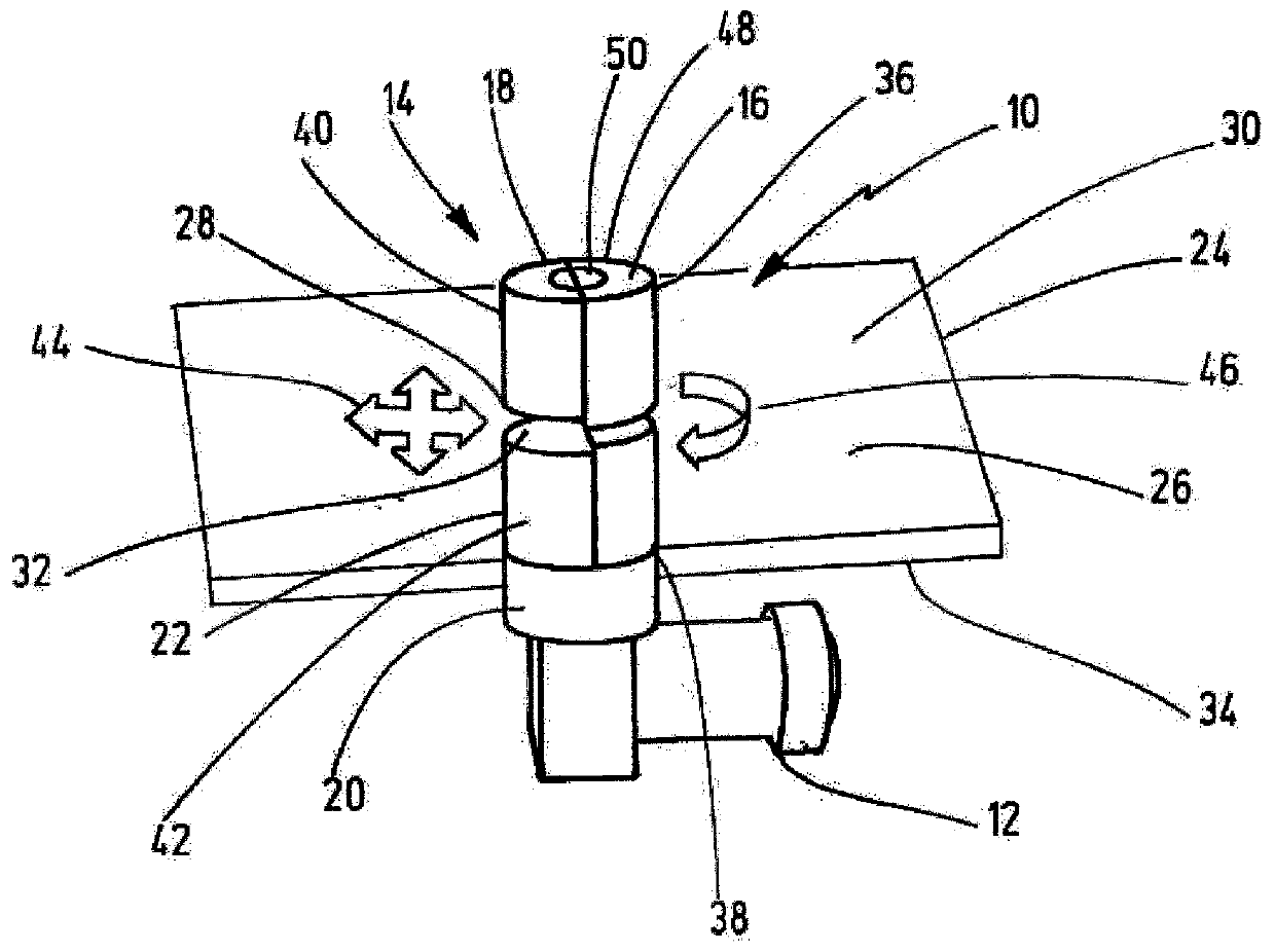
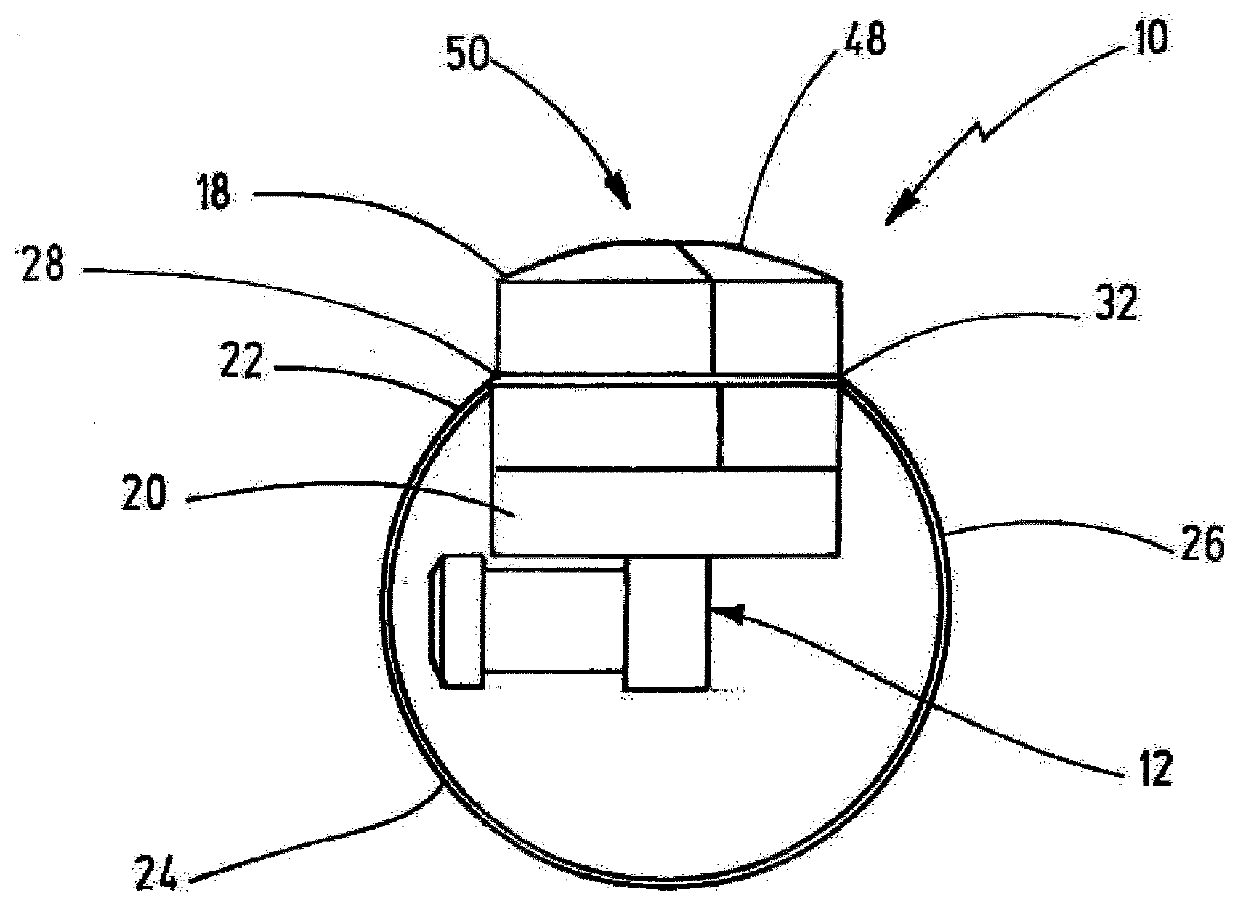
[0023] figure 1 A device for aligning the optical unit 12 is shown schematically with the reference number 10 . The device 10 comprises an adjustment device 14 having an actuation member 16 . The actuation member 16 is formed by a radially magnetized ring magnet 18 .

[0024] The optical unit 12 is arranged on the carrier part 20 . The carrier part 20 comprises a radially magnetized ring magnet 22 . Ring magnet 18 and ring magnet 22 are disposed on opposite sides of housing 24 .

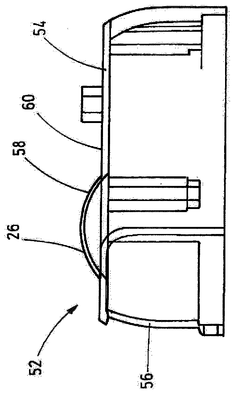
[0025] only at figure 1 The middle part shows the housing 24 and the housing 24 forms an adjustment area 26 . Housing 24 or adjustment region 26 is arranged between ring magnet 18 and ring magnet 22 . exist figure 1 In , for the sake of clarity, the dotted line indicates that the parts below the housing 24 are omitted.

[0026] according to figure 1 , the ring magnet 16 adjoins the upper surface 30 of the adjusting region 26 with its lower end surface 28 . The ring magnet 22 adjoins with it...


PUM


Abstract

The invention relates to a device (10) for orientation of an optical unit (12) of a camera (52, 70), said optical unit being arranged inside a housing (24, 4, 72), relative to a mounting location of the camera, the device including adjustment means (14), the actuating part (16) of which is operatively connected to a supporting part (20) of the optical unit (12). The actuating part (16) is arrangedoutside the housing (24, 54, 72) and the supporting part (20) is arranged inside the housing (24, 54, 72), and the actuating part (16) and the supporting part (20) each comprise a diametrically magnetized magnet (18, 22) at least on their mutually facing sides. According to the invention, this is a rear-view mirror camera (52), side- and / or rear-view camera (70) for road and / or rail vehicles.

Description

technical field [0001] The invention relates to a device for orienting an optical unit of a camera, which is arranged inside a housing, relative to the installation position of the camera. It is known to mount cameras for different intended uses in a fixed manner at installation locations. For example, this may occur on the walls of buildings or in vehicles (for example on the bodywork of rail vehicles or road vehicles). Depending on the intended use of the camera, the optical unit is intended to detect a certain part of the environment of the installation location. In a vehicle these may be, for example, a rear view camera, a side view camera and / or a reversing camera. Background technique [0002] The housing in which the camera's optical and / or electronic components are located is usually rigidly attached to the mounting location. The optical unit of the camera must be oriented inside the housing to the desired environment to be monitored. It is known to accommodate o...

Claims


Application Information

Patent Timeline
IPC IPC(8): G03B17/00G08B13/00G05D3/00G12B5/00
CPCG03B17/00G12B5/00G03B2215/00G08B29/20
Inventor 迈克尔·韦伯
Owner DRES FAHRZEUGELEKTRONIK GMBH
Why Eureka
Try Eureka