
Automatic numerical control machine tool

A technology of CNC machine tools and machine tools, which is applied in the directions of metal processing mechanical parts, clamping and supporting, which can solve the problems of difficult cleaning, large storage volume and falling of tool changing equipment, and achieve rapid installation and use, and improve processing efficiency. Effect

Active Publication Date: 2020-07-28
杭州智科精密机械有限公司
View PDF7 Cites 4 Cited by
  • Summary
  • Abstract
  • Description
  • Claims
  • Application Information

AI Technical Summary

Problems solved by technology

[0003] During the working process of the CNC machine tool, the tool needs to be replaced frequently. However, the speed of tool change is relatively slow at present, and the tool holder needs to be moved to the tool changing device for tool change operation, which makes the processing efficiency of the CNC machine tool low. Moreover, the tool changing equipment needs to store a larger volume, a complex structure, and a higher cost
[0004] Moreover, during the cutting process of CNC machine tools, a large amount of iron filings will be generated. Now, in the process of processing, iron filings are generally cleaned by using an iron filings vacuum cleaner, but this method cannot guarantee that the iron filings can be cleaned better , the iron filings may fall to every corner of the machine tool, which makes it difficult to clean up later, especially if the iron filings enter the servo drive structure of the CNC machine tool, it will seriously affect the operation of the CNC machine tool

Method used


Image

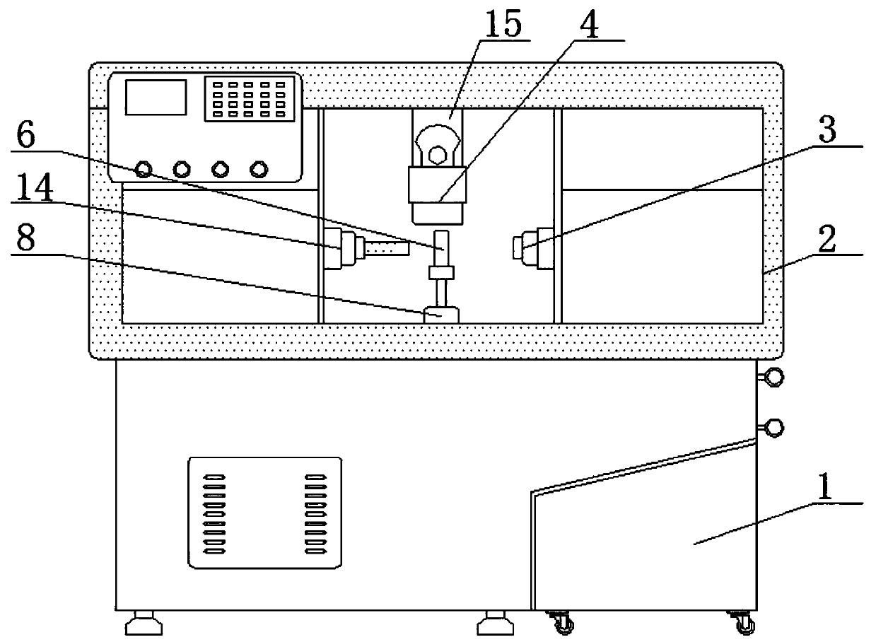
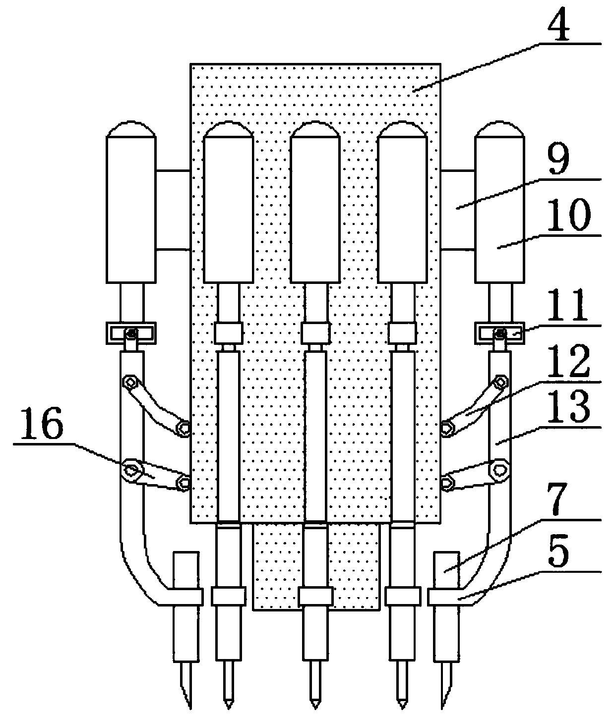
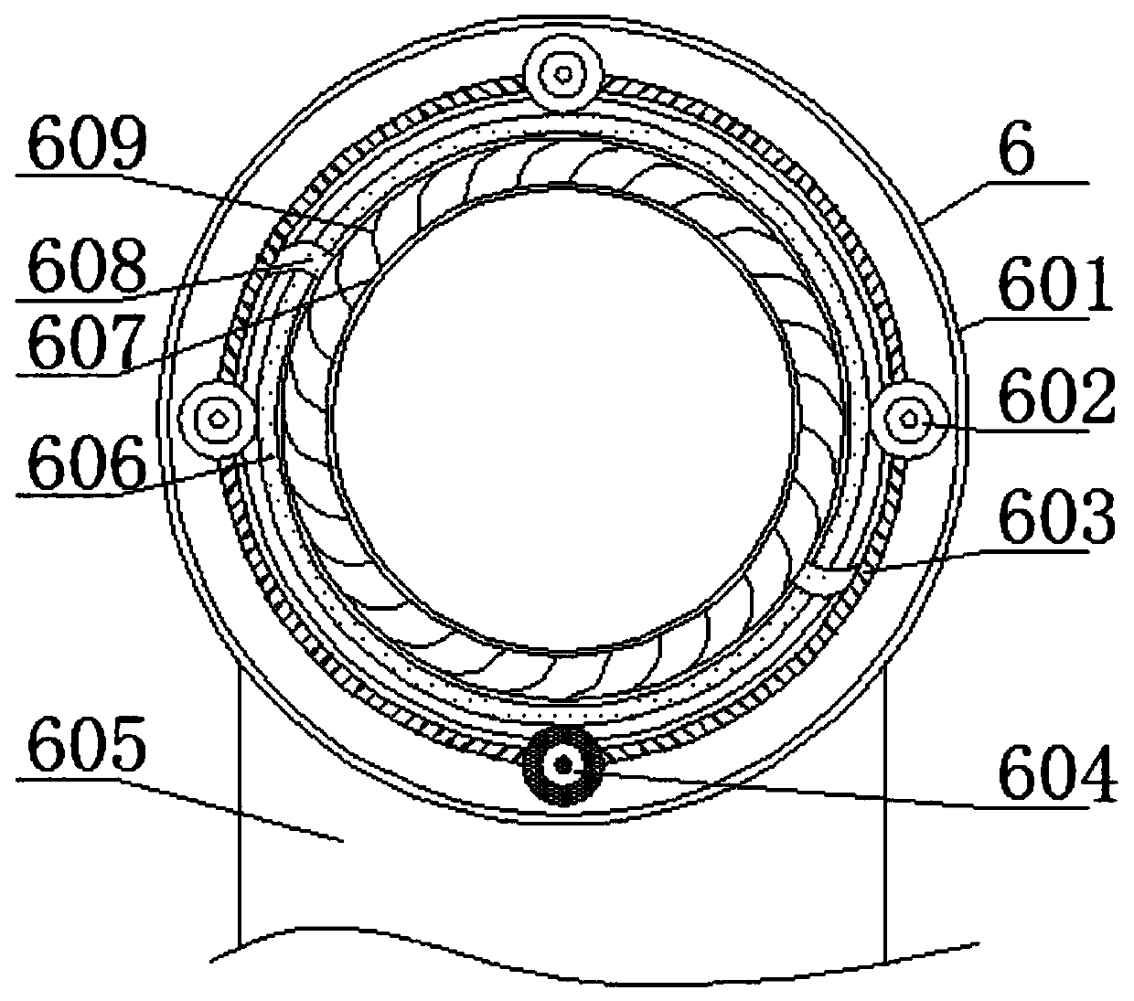
  • Automatic numerical control machine tool
  • Automatic numerical control machine tool
  • Automatic numerical control machine tool

Examples


Embodiment Construction

[0021] The following will clearly and completely describe the technical solutions in the embodiments of the present invention with reference to the accompanying drawings in the embodiments of the present invention. Obviously, the described embodiments are only some, not all, embodiments of the present invention. Based on the embodiments of the present invention, all other embodiments obtained by persons of ordinary skill in the art without making creative efforts belong to the protection scope of the present invention.

[0022] see Figure 1-5 , an automated numerical control machine tool, comprising a machine base 1, a workbench 2 is fixedly installed on the top of the machine base 1, a mobile table 15 is fixedly installed on the top of the inner cavity of the workbench 2, and a tool rest device 4 is movably installed on the front of the mobile table 15 The side of the knife rest device 4 is fixedly equipped with a connecting seat 9, and the other end of the connecting seat 9...


PUM


Abstract

The invention relates to the technical field of machine tool equipment and discloses an automatic numerical control machine tool. The automatic numerical control machine tool comprises a machine toolbase. A worktable is fixedly mounted on the top of the machine tool base, a mobile table is fixedly mounted on the top of an inner cavity of the worktable, a knife rest device is movably mounted on the front surface of the mobile table, a connecting seat is fixedly mounted on the side surface of the knife rest device, a hydraulic rod is fixedly mounted at the other end of the connecting seat, andan inner sliding seat is fixedly mounted at the bottom of the hydraulic rod. According to the automatic numerical control machine tool, by arranging the hydraulic rod, a connecting rod, a bending rodand he mobile seat on the side surface of the knife rest device, a tool on a clamping seat can be placed below the knife rest device quickly, so that the tool is mounted and used quickly. Further, a special tool changing device is not needed by the equipment, and it is not needed to move the knife rest device to the tool changing device to change the tool, so that the machining efficiency of the machine tool is improved.

Description

technical field [0001] The invention relates to the technical field of machine tool equipment, in particular to an automatic numerical control machine tool. Background technique [0002] Numerical control machine tool is the abbreviation of digital control machine tool, which is an automatic machine tool equipped with a program control system, which can logically process programs with control codes or other symbolic instructions, and decode them, using coded numbers It means that the numerical control device is input through the information carrier, and various control signals are sent by the numerical control device after calculation and processing to control the movement of the machine tool, and the parts are automatically processed according to the shape and size required by the drawing. [0003] During the working process of the CNC machine tool, the tool needs to be replaced frequently. However, the speed of tool change is relatively slow at present, and the tool holder...

Claims


Application Information

Patent Timeline
IPC IPC(8): B23Q3/155B23Q11/00
CPCB23Q3/155B23Q11/0042
Inventor 不公告发明人
Owner 杭州智科精密机械有限公司
Learn More