
A single-layer cross-coupled filter

A cross-coupling and filter technology, which is applied in the field of filters, can solve problems affecting filter performance and height increase, and achieve the effects of improving design flexibility, reducing processing and assembly costs, and reducing processing and assembly tolerances

Active Publication Date: 2022-04-08
PROSE TECH CO LTD
View PDF10 Cites 0 Cited by
  • Summary
  • Abstract
  • Description
  • Claims
  • Application Information

AI Technical Summary

Problems solved by technology

This bending will increase the height of the overall product, and the amount of solder and soldering position during soldering will also affect the performance of the filter

Method used


Image

  • A single-layer cross-coupled filter
  • A single-layer cross-coupled filter
  • A single-layer cross-coupled filter

Examples


Embodiment Construction

[0034] The technical solutions of the embodiments of the present invention will be clearly and completely described below in conjunction with the accompanying drawings of the present invention.

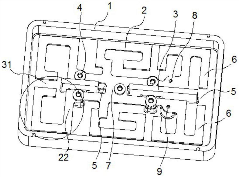
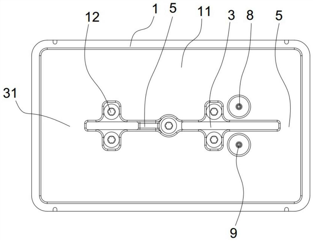
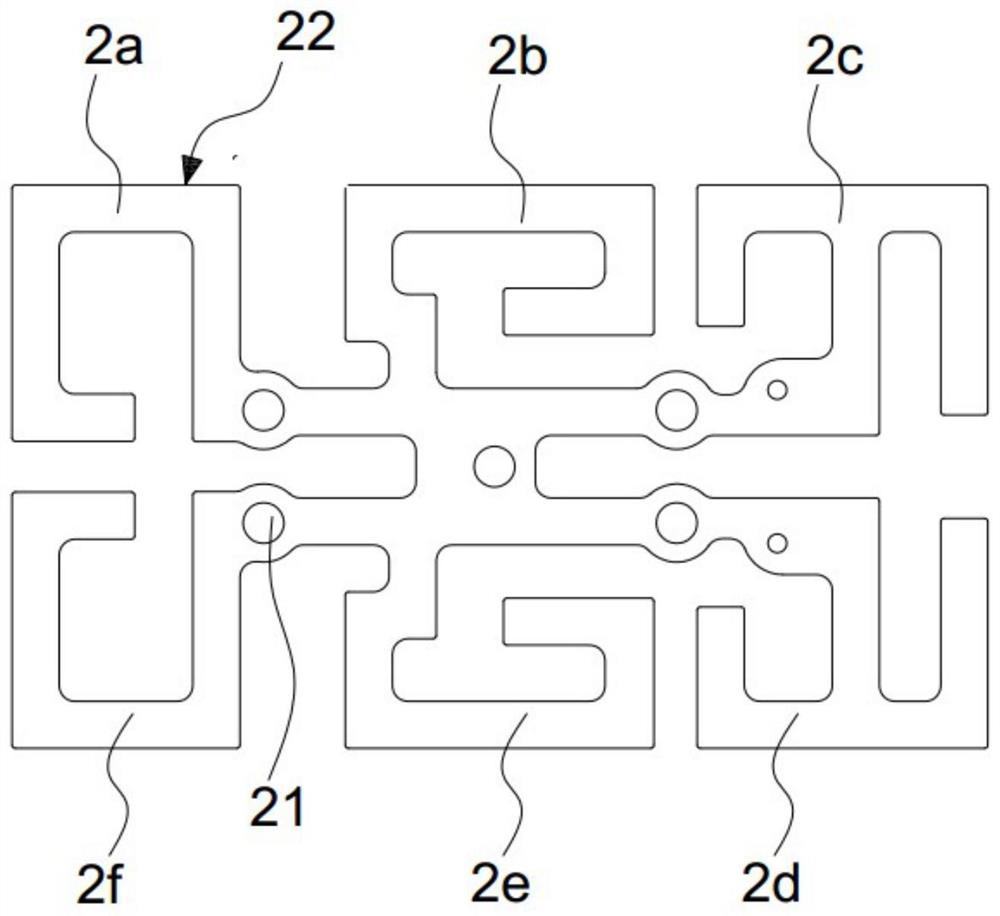
[0035] A single-layer cross-coupled filter disclosed by the present invention, through the improved design of the resonator shape, a single-layer resonant unit structure composed of the resonator is integrally formed, and non-adjacent parts of the single-layer resonant unit structure Adding cross-coupling between resonators can realize the miniaturization of the filter at the same time: 1. There is no need to add additional conductors to achieve cross-coupling, which reduces processing and assembly costs, as well as processing and assembly tolerances; 2. In non-phase The cross-coupling between adjacent resonators can be controlled separately, so the design and manufacture become simple; 3. Compared with the multi-layer structure, the single-layer cross-coupling reduces the overall heig...


PUM


Abstract

The invention discloses a single-layer cross-coupling filter, which includes a cavity, a resonant structure and a partition wall. The resonant structure is integrally formed and installed in the cavity. There are at least two rows of resonant units on the plane, and each row of resonant units includes a plurality of resonators; the partition wall is arranged between two adjacent rows of resonant units, and a coupling window is formed on it, and two adjacent resonators in different rows Cross-coupling is formed between the corresponding coupling windows. While realizing the miniaturization of the filter, the invention also reduces the cost of processing and assembly, as well as the tolerance of processing and assembly.

Description

technical field [0001] The invention relates to a filter, in particular to a single-layer cross-coupling filter. Background technique [0002] As the filter is miniaturized, lightweight or implemented on a dielectric plane such as PCB (Printed Circuit Board) or Alumina (alumina), planar air stripline or comb line resonators are usually used The one-word structure has many restrictions on the realization of cross-coupling. The general way to achieve cross-coupling is to add anti-phase coupling to the transmission path to generate zero points. [0003] Such as Figure 7 As shown, in a 4-cavity filter composed of four resonators, when the signal is transmitted through inductive coupling in resonator 1-2-3-4, in the inductive coupling transmission path of resonator 1-2-3-4 sequence Increasing the capacitive coupling of resonators 1-4 will give Figure 8 In the passband, the low frequency and high frequency of the passband produce two zero points due to the opposite phase. Thi...

Claims


Application Information

Patent Timeline
Patent Type & Authority Patents(China)
IPC IPC(8): H01P1/20H01P1/208
CPCH01P1/20H01P1/208
Inventor 李敦穁罗仁虎尹泽卢坚
Owner PROSE TECH CO LTD
Learn More