Device for directionally distributing steel fibers and application thereof

A directional distribution and steel fiber technology, which is applied in the processing of building materials, construction, building construction, etc., can solve the problems of uneven distribution of upper and lower layers of fibers, agglomeration of steel fibers, and poor results, so as to improve tensile performance and The effect of toughness, quick and easy installation

Inactive Publication Date: 2020-07-17
TONGJI UNIV
View PDF5 Cites 5 Cited by
  • Summary
  • Abstract
  • Description
  • Claims
  • Application Information

AI Technical Summary

Problems solved by technology

In actual engineering, steel fibers are generally directly mixed into concrete or cement mortar, and then dispersed evenly by stirring. However, since the steel fibers are prone to agglomeration and random distribution in the slurry, the tensile strength of the steel fibers is significantly reduced. Properties and Toughening Effect
[0004] The existing technology uses a uniform magnetic field to realize the directional distribution of steel fibers in concrete, but it is difficult for the steel fibers in the lower layer to be oriented due to the influence of the pressure of the upper layer of concrete, and the steel fibers settle down due to gravity, so that the distribution of fibers in the upper and lower layers is uneven. Therefore, it can only be adapted to the single-layer steel fiber distribution design, and the effect is not good for concrete that usually requires three-dimensional and multi-layer fibers.

Method used


Image

  • Device for directionally distributing steel fibers and application thereof
  • Device for directionally distributing steel fibers and application thereof
  • Device for directionally distributing steel fibers and application thereof

Examples


Embodiment Construction

[0022] In order to make the technical means, creative features, goals and effects achieved by the present invention easy to understand, the present invention will be described in detail below in conjunction with the embodiments and accompanying drawings.

[0023]

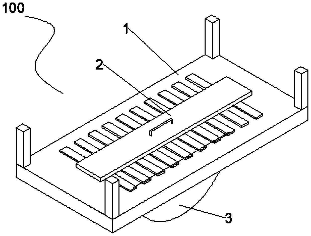
[0024] figure 1 It is a schematic diagram of the overall structure of a device for directional distribution of steel fibers in an embodiment of the present invention.

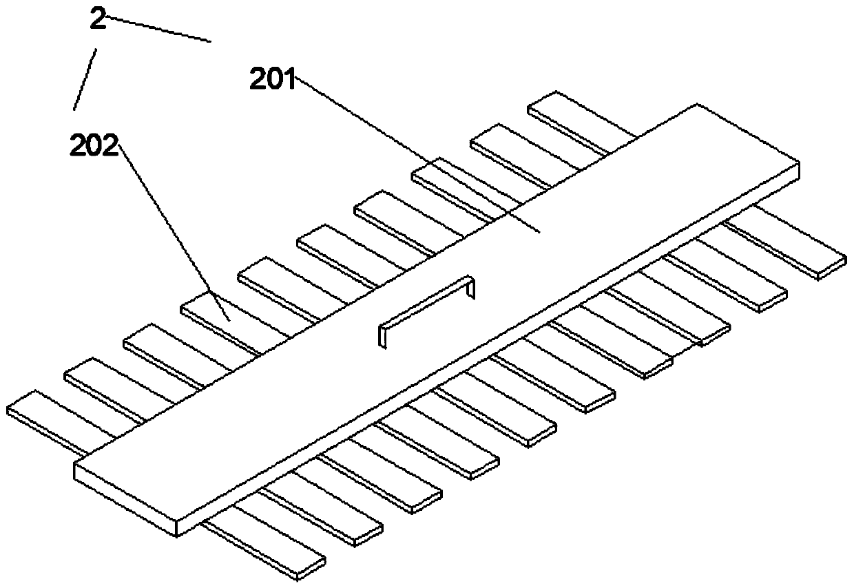
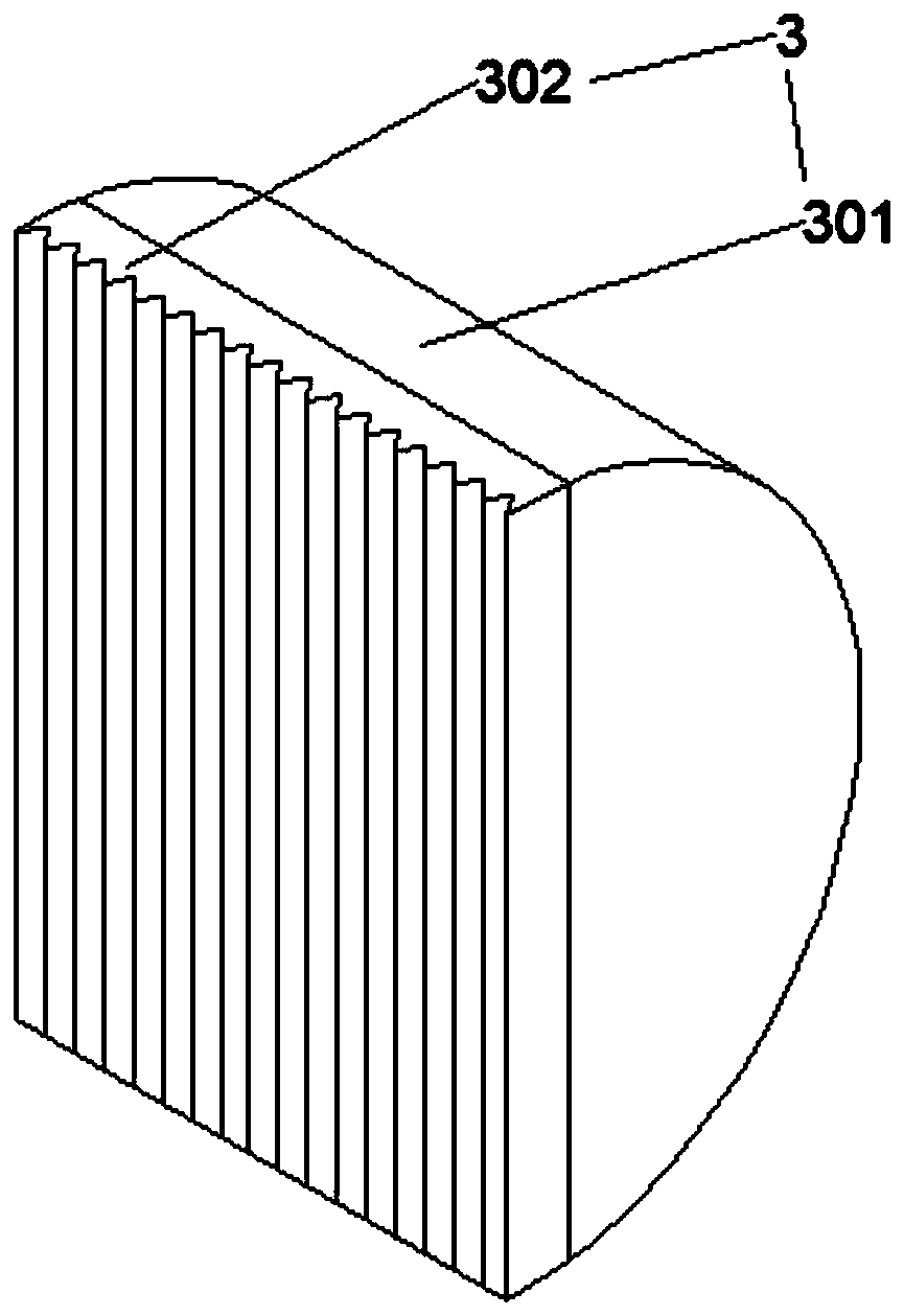
[0025] Such as Figure 1 to Figure 3 As shown, this embodiment provides a device for directional distribution of steel fibers, which is used for directional distribution of steel fibers in cement slurry. A device 100 for directionally distributing steel fibers includes: a glass plate 1 , a magnet block 2 and a clamping piece 3 .

[0026] Glass plate 1 is used to place steel fibers. The thickness of the glass plate 1 is 5 mm. The thickness of the glass plate 1 is related to the magnetic force of the magnet block 2, the stronger the magnetic forc...


PUM

PropertyMeasurementUnit
thicknessaaaaaaaaaa
thicknessaaaaaaaaaa
diameteraaaaaaaaaa

Abstract

The invention relates to the field of buildings, and discloses a device for directionally distributing steel fibers. The device is used for directionally distributing the steel fibers in cement paste.The device comprises a glass plate, a magnet block and a clamping piece, wherein the top surface of the glass plate is used for placing the steel fibers; the magnet block is positioned below the glass plate and used for uniformly and directionally distributing the steel fibers; and the clamping piece is used for moving the directionally distributed steel fibers into the cement paste. When the steel fibers are placed near a magnet, the steel fibers can be directionally arranged in the direction of a magnetic induction line under the action of a magnetic field force, meanwhile, the steel fiberscan also be magnetized in a magnetic field, the steel fibers with magnetism are formed, the steel fibers on the same column attract each other due to the action of magnetic poles, and the directionalcontinuity of steel fiber arrangement is guaranteed. The steel fibers on different columns repel each other due to the action of the magnetic poles, due to the fact that the fiber specifications areconsistent, the repulsive force is basically the same, the distances between the steel fibers on different columns are roughly the same, and therefore the tensile property and the toughening effect ofa steel fiber reinforced cement-based material are improved.

Description

technical field [0001] The embodiments of the present invention relate to the construction field, and in particular to a device for directionally distributing steel fibers and its application. Background technique [0002] Adding a higher amount of steel fiber into the concrete can prepare ultra-high performance concrete, which has very excellent mechanical properties, and its mechanical properties such as bending resistance, tensile strength, shear resistance, and fracture toughness are significantly higher than those of traditional reinforced concrete. . Relevant studies have shown that the volume content and direction coefficient of steel fibers in concrete are important factors affecting its performance. In addition, the uniform distribution of steel fibers can also significantly improve the flexural strength and compressive strength of concrete and cement mortar, and effectively improve the impact resistance. [0003] Regarding the uniform and directional distribution...

Claims


Application Information

Patent Timeline
Patent Type & Authority Applications(China)
IPC IPC(8): E04G21/00C04B14/48
CPCC04B14/48E04G21/00
Inventor 朱洪波苟鸿翔杨正宏
Owner TONGJI UNIV
Why Eureka
Try Eureka