


Quick Research
Generate reliable direction feasibility study reports for your R&D in just a few steps.

Technical Q&A
Discover and master advanced knowledge NOW. Basics, ideas, possibilities, all at once.

Find Solutions
As an expert in R&D theories, this can generate solutions to your technical problems instantly.

Evaluate Feasibility
Analyze your overall solution with one click, know your potential R&D risks in advance.

Monitor Landscape
Get weekly tech updates, stay abreast of the latest tech innovations and key insights.
Polymer electrolyte membrane, method for manufacturing same, and membrane electrode assembly comprising same
An electrolyte membrane, polymer technology, applied in electrolytes, non-aqueous electrolytes, solid electrolytes, etc., can solve the problems of low free radical stability, weak free radical resistance, high hydrogen permeability, and achieve excellent durability and ion conductivity. , the effect of reducing hydrogen permeability
- Summary
- Abstract
- Description
- Claims
- Application Information
AI Technical Summary
Problems solved by technology
Method used
Image

Examples
preparation example Construction
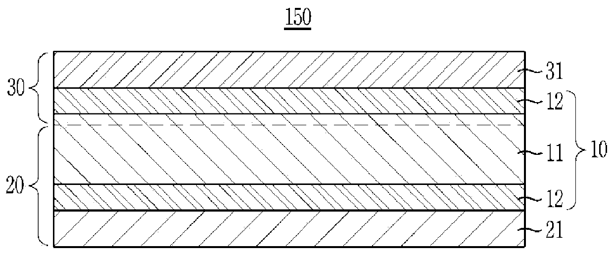
[0198] A method for preparing a polymer electrolyte membrane according to another embodiment of the present disclosure includes: preparing a fluorine-based carrier having a plurality of pores formed by a microstructure of polymer fibrils; Or forming a nanonet on both surfaces, the nanonet including nanofibers integrated with a nonwoven fabric having a plurality of pores, thereby preparing a hybrid composite porous carrier; and filling the pores of the hybrid composite porous carrier with ion conductors.
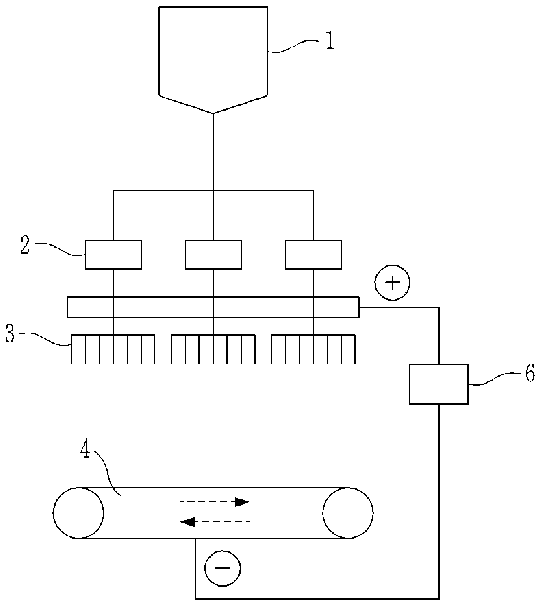
[0199] Fluorinated polymers with multiple pores due to the microstructure of polymer fibrils were prepared as follows. Specifically, in the presence of a lubricant such as solvent naphtha or white oil, PTFE powder prepared by dispersion polymerization is extruded into a stick paste, and the stick paste extrudate (cake) is rolled to prepare Sintered PTFE sheet. The green PTFE sheet is stretched at a predetermined ratio in the machine direction (MD) and / or the transverse direc...
preparation Embodiment 1
[0250] [Preparation Example 1: Preparation of Ion Conductor]
preparation Embodiment 1-1
[0252] 1) Preparation of hydrophobic repeating units
[0253] As shown in Equation 3 below, bisphenol A was reacted with 1,3-bis(4-fluorobenzoyl)benzene at 160°C to 180°C for 30°C using a co-solvent of DMAc / toluene in the presence of potassium carbonate. hours, the resulting reaction solution was washed with purified water, and then dried with hot air. At this time, the degree of polymerization of the oligomer is controlled using the Carothers equation.
[0254] [reaction formula 3]
[0255]
[0256] 2) Preparation of hydrophilic repeating units
[0257] As shown in Scheme 4 below, 4,4'-(9-fluorenylidene)biphenol was reacted with bis(4-fluorophenyl)sulfone at 160 °C using a co-solvent of DMAc / toluene in the presence of potassium carbonate After reacting at 180°C for 30 hours, the obtained reaction solution was washed with purified water, and then dried with hot air. At this time, the degree of polymerization of the oligomer is controlled using the Carothers equation...
PUM
| Property | Measurement | Unit |
|---|---|---|
| diameter | aaaaa | aaaaa |
| base weight | aaaaa | aaaaa |
| porosity | aaaaa | aaaaa |
Abstract
Description
Claims
Application Information
 - R&D Engineer
- R&D Manager
- IP Professional
- Industry Leading Data Capabilities
- Powerful AI technology
- Patent DNA Extraction
Browse by: Latest US Patents, China's latest patents, Technical Efficacy Thesaurus, Application Domain, Technology Topic, Popular Technical Reports.
© 2024 PatSnap. All rights reserved.Legal|Privacy policy|Modern Slavery Act Transparency Statement|Sitemap|About US| Contact US: help@patsnap.com