


Quick Research
Generate reliable direction feasibility study reports for your R&D in just a few steps.

Technical Q&A
Discover and master advanced knowledge NOW. Basics, ideas, possibilities, all at once.

Find Solutions
As an expert in R&D theories, this can generate solutions to your technical problems instantly.

Evaluate Feasibility
Analyze your overall solution with one click, know your potential R&D risks in advance.

Monitor Landscape
Get weekly tech updates, stay abreast of the latest tech innovations and key insights.
Neutron counting method used in strong pulse X-ray environment and counter
A counting method, X-ray technology, applied in radiation measurement, neutron radiation measurement, instruments, etc., can solve the problem of inaccurate neutron counting and achieve the effect of improving accuracy
- Summary
- Abstract
- Description
- Claims
- Application Information
AI Technical Summary
Problems solved by technology
Method used
Image

Examples
Embodiment 1
[0037] Such as Figure 1 to Figure 4 As shown, the present invention provides a neutron counting method used in a strong pulsed X-ray environment, including: a moderator 1, a proportional counter tube 2, an isolation resistor R5, an isolation capacitor C3, an amplifier circuit 5, a cable 3 and a pulse power supply Circuit 4.
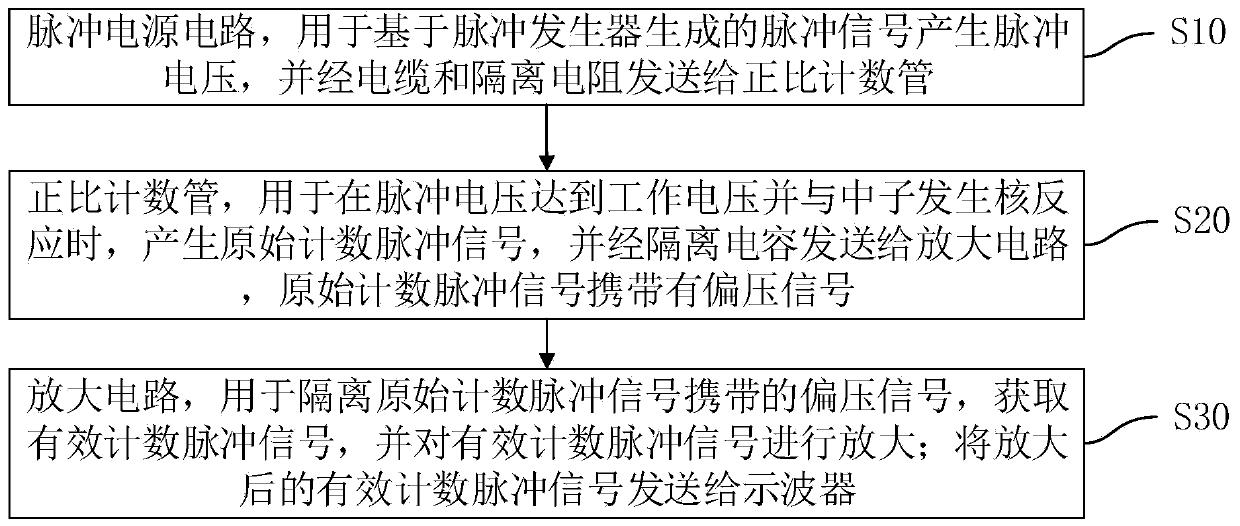
[0038] S10: pulse power supply circuit 4, used to generate pulse voltage based on the pulse signal generated by the pulse generator, and send it to the proportional counter tube 2 through the cable 3 and the isolation resistor R5.
[0039] Specifically, the isolation resistor R5 is a resistor with a resistance value of 10k-100k ohms, one end of which is connected to the anode of the proportional counter tube 2, and the other end is connected to the pulse power supply circuit 4 through the cable 3, and its function is to make the pulse power supply circuit 4 be Proportional counter tube 2 applies pulse voltage, and at the same time isolates the count pul...
Embodiment 2
[0066] Such as Figure 4 As shown, the difference between this embodiment and Embodiment 1 is that a neutron counter based on the above-mentioned neutron counting method used in a strong pulsed X-ray environment, the neutron counter includes:
[0067] The proportional counter tube 2 is set in the moderator 1, the cathode of the proportional counter tube 2 is connected to the moderator 1, and the anode of the proportional counter tube 2 is respectively connected to the isolation resistor R5 and the isolation capacitor C3; the isolation resistor R5 is connected to the pulse by the cable 3 The power supply circuit 4 is connected, and the isolation capacitor C3 is connected with the amplifier circuit 5 .
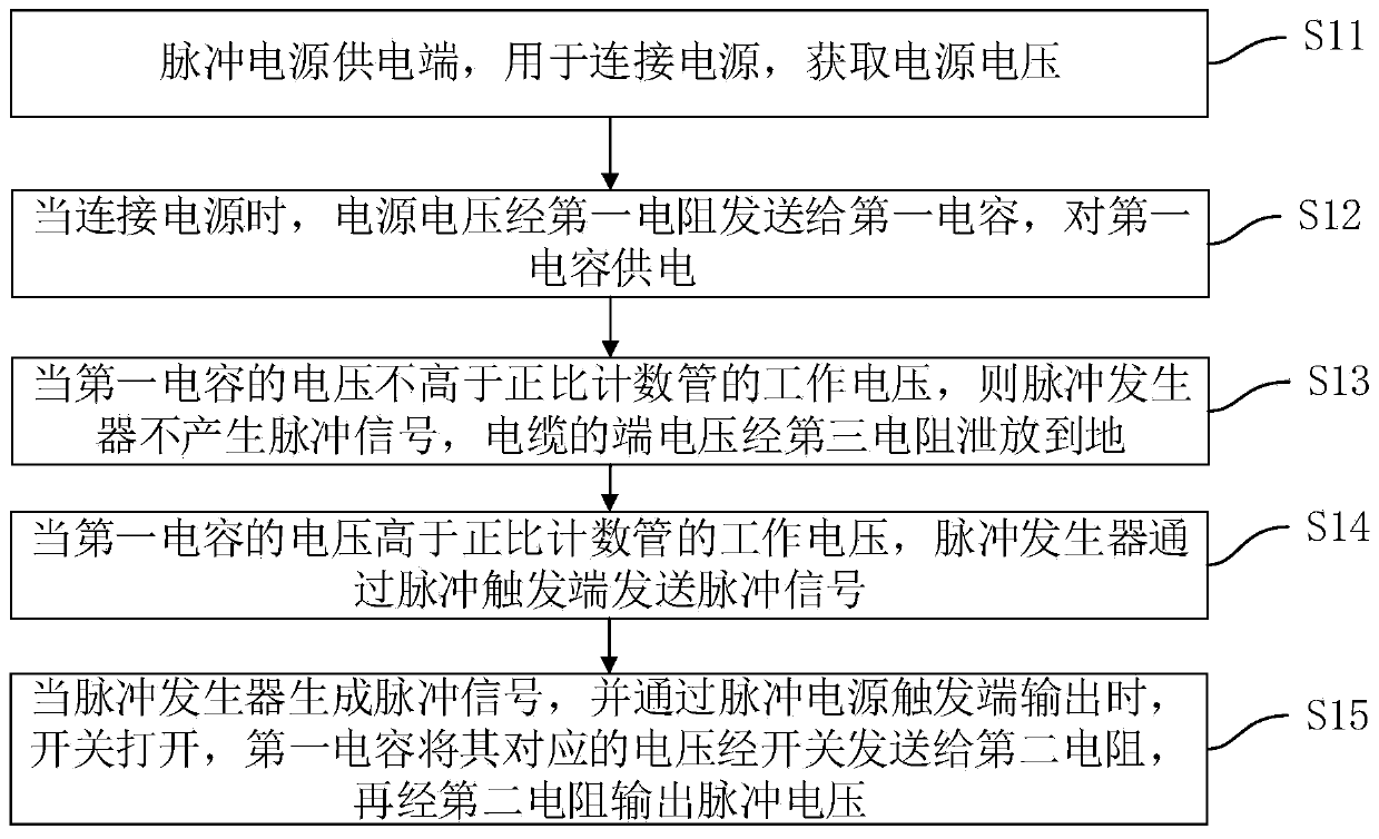
[0068] Further, the pulse power supply end is connected to one end of the first resistor R1, the other end of the first resistor R1 is respectively connected to one end of the first capacitor C1 and the first end of the switch K1, the other end of the first capacitor C1 is groun...
PUM
 Abstract
Description
Claims
Application Information
 - R&D Engineer
- R&D Manager
- IP Professional
- Industry Leading Data Capabilities
- Powerful AI technology
- Patent DNA Extraction
Browse by: Latest US Patents, China's latest patents, Technical Efficacy Thesaurus, Application Domain, Technology Topic, Popular Technical Reports.
© 2024 PatSnap. All rights reserved.Legal|Privacy policy|Modern Slavery Act Transparency Statement|Sitemap|About US| Contact US: help@patsnap.com