
Tin coating nozzle and device

A nozzle and soldering technology, applied in the field of integrated circuit welding, can solve the problems of inability to meet the requirements of tin plating, tin connection, short circuit of integrated circuit pins, etc., and achieve the effect of avoiding the phenomenon of tin connection

Pending Publication Date: 2020-07-10
SHENZHEN ANEWBEST ELECTRONICS TECH
View PDF0 Cites 0 Cited by
  • Summary
  • Abstract
  • Description
  • Claims
  • Application Information

AI Technical Summary

Problems solved by technology

[0003] At present, the flat water curtain tin film formed by the nozzle usually used in tinning equipment can only meet the minimum pitch of 0.3mm for tinning. However, the minimum pin spacing of common integrated circuits is 0.2mm.
At the same time, with the development trend of integrated circuits, the functions of integrated circuits are becoming larger and larger, their area is limited, and the density of integrated circuit pins is increasing. The use of existing technologies is likely to cause solder connection between two pins, resulting in integrated circuits. There is a short circuit between the circuit pins. Therefore, it can neither meet the requirements of the pins of the existing integrated circuits to remove gold and tin, nor can it meet the requirements of the development trend of integrated circuits for tin plating.

Method used


Image

  • Tin coating nozzle and device
  • Tin coating nozzle and device
  • Tin coating nozzle and device

Examples


Embodiment Construction

[0025] The claims of the present invention will be further described in detail below in conjunction with specific embodiments and accompanying drawings. Apparently, the described embodiments are only some of the embodiments of the present invention, not all of them. Based on the embodiments of the present invention, all other embodiments obtained by persons of ordinary skill in the art without creative work also fall within the protection scope of the present invention.

[0026] It should be understood that in the description of the present invention, all directional terms, such as "up", "down", "left", "right", "front", "rear", etc. indicate the orientation or positional relationship Based on the orientation or positional relationship shown in the drawings or the conventional orientation or positional relationship of the invention product in use, it is only for the convenience of describing the present invention and simplifying the description, rather than indicating or implyi...


PUM


Abstract

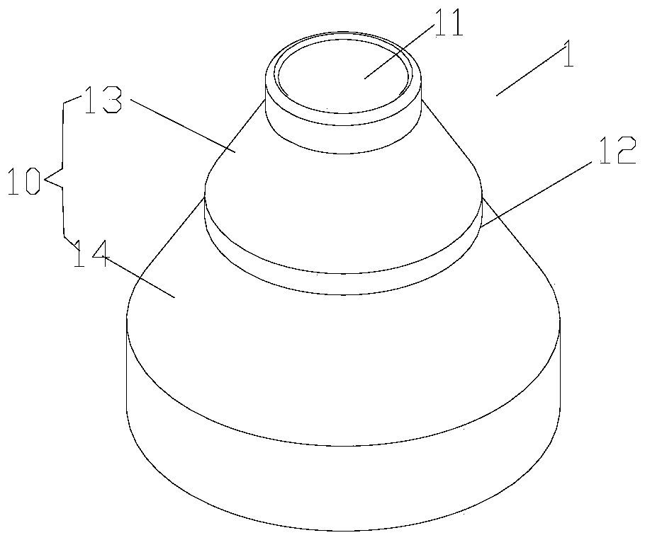
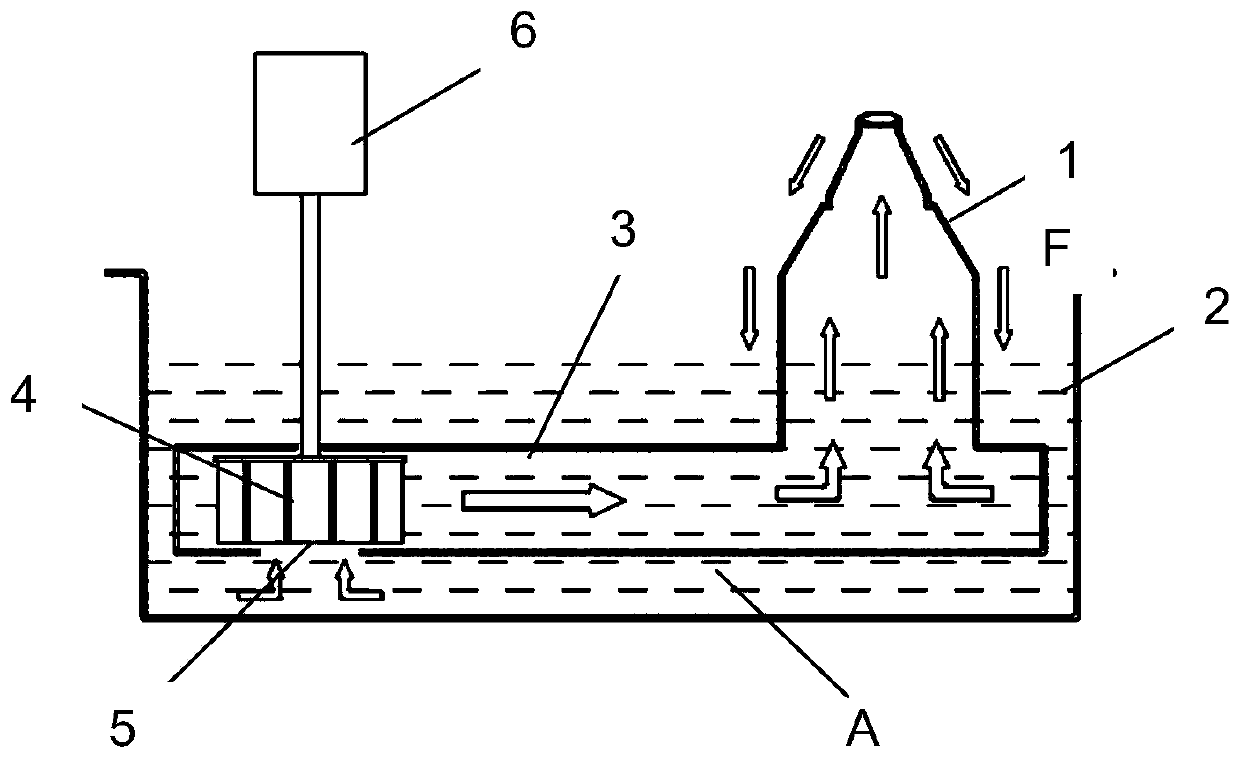
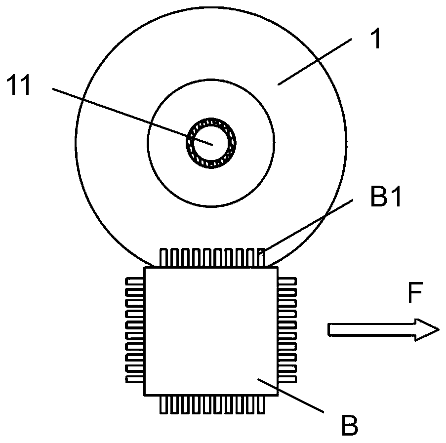
The method is suitable for the technical field of integrated circuit welding, and discloses a tin coating nozzle and a tin coating device. The tin coating nozzle comprises a nozzle body provided witha tin outlet, the nozzle body is provided with an arc-shaped inclined plane enabling liquid soldering tin to flow from the surface of the nozzle body to form a soldering tin film, and the thickness ofthe soldering tin film is gradually reduced from top to bottom. Due to the fact that the arc-shaped inclined face is arranged on the outer side surface of the nozzle body, when the tin outlet amountis constant, a tin film which is gradually thinned from top to bottom is formed when tin flows through the nozzle body with the arc-shaped inclined face. During tin coating, the positions of pins passing through the tin film are determined according to the density of the pins for tin coating, it can be guaranteed that the contact area between the pin faces of a device and the arc-shaped inclined face is small through the surface arc face structure during tin coating, meanwhile, under the combined action of momentum generated in the process that tin flows from top to bottom, the continuous tinphenomenon is not likely to be formed between the two pins in the tin coating process, and the continuous tin phenomenon during enameling welding is avoided.

Description

technical field [0001] The invention relates to the technical field of integrated circuit welding, in particular to a tinning nozzle and a device. Background technique [0002] Pre-soldering is to pre-wet the lead wires of the components to be soldered or the conductive soldering parts with solder, generally also known as tinning, tinning, tinning or hanging tin. There are two main types of tin tanning machines: ordinary tin tanning machine and ultrasonic tin tanning machine. Due to the different sizes and distribution densities of tinned pins, the difficulty of tinned process varies. [0003] At present, the flat water-curtain tin film formed by the spout commonly used in tinning equipment can only meet the minimum pitch of 0.3mm for tinning. However, the minimum pin spacing of common integrated circuits is 0.2mm. At the same time, with the development trend of integrated circuits, the functions of integrated circuits are becoming larger and larger, their area is limited,...

Claims


Application Information

Patent Timeline
IPC IPC(8): B23K3/00B23K3/06B23K3/08
CPCB23K3/00B23K3/0607B23K3/082
Inventor 周旋王海英檀正东王海明蔡云峰朱继元罗小军尹帮前
Owner SHENZHEN ANEWBEST ELECTRONICS TECH
Learn More