Novel oscillating cylinder hydraulic system of boom pump truck and concrete pump truck

A boom pump truck and hydraulic system technology, which is applied in the direction of fluid pressure actuators, servo motors, servo meter circuits, etc., can solve problems such as high pumping pressure, lower pressure, and affect the construction process, so as to prevent oil circuit backflow , improve stability and reduce impact

Inactive Publication Date: 2020-07-03
QINGDAO JIUHE HEAVY IND MACHINERY
View PDF11 Cites 0 Cited by
  • Summary
  • Abstract
  • Description
  • Claims
  • Application Information

AI Technical Summary

Problems solved by technology

At present, the focus of competition of foreign and domestically produced boom pump trucks is the technical level of the product, such as boom swing cylinder impact, noise, stability and service life. When pumping concrete, the concrete pump truck pumps through two main cylinders Push the concrete pistons in the two delivery cylinders to reciprocate respectively, and the concrete pistons are retracted under the drive of the main pumping cylinder, so that the concrete is sucked into the delivery cylinder, while the concrete piston in the other delivery cylinder is pumping the main oil cylinder. Driven to extend out, so as to push out the concrete that was pre-sucked in the previous stroke, so as to complete the pumping. In order to ensure the continuity of pumping, it is realized through the swing cylinder hydraulic system. Two main pumping cylinders drive a concrete piston respectively. The concrete can be continuously pumped out by reciprocating operation and alternating directions in the conveying cylinder. The concrete pumped by the ultra-high pressure concrete pump has low slump and poor fluidity, so the pumping pressure is very high and the pumping is difficult. Carelessness can easily cause the concrete to move and block the pipe, affecting the construction process; Chinese patent 201220248606.3 discloses a concrete pump swing cylinder hydraulic system, including a hydraulic pump, a first accumulator, a hydraulic cylinder, a reversing valve and a hydraulic The first one-way valve connected to the outlet of the pump, wherein the first one-way valve is connected to the hydraulic cylinder through the reversing valve, the first accumulator is arranged on the oil circuit connecting the first one-way valve and the reversing valve, and the hydraulic pressure of the swing cylinder The system also includes an overflow unit, which is used to reduce the pressure at the outlet of the hydraulic pump when the pressure of the first accumulator reaches a predetermined value, or the swing cylinder hydraulic system also includes an energy storage unit, which is used to When the pressure of the first accumulator reaches a predetermined value, the hydraulic oil output by the hydraulic pump is stored; Chinese patent 201410318934.X discloses a positive and negative pump switching hydraulic system of a concrete pump and a concrete pump truck. The positive and negative pump switching hydraulic system includes The swing cylinder group, the first reversing valve group, the second reversing valve group, the first electromagnetic reversing valve and the main oil cylinder group, the first reversing valve group feeds and returns oil to the swing cylinder group through the control oil circuit, and controls The moving direction of the piston of the swing cylinder group, the second reversing valve group feeds and returns oil to the main oil cylinder group through the control oil circuit, and controls the moving direction of the piston of the main oil cylinder group; the main oil cylinder group feeds the first electromagnetic reversing valve Oil, oil return, the first electromagnetic reversing valve controls the working position of the first reversing valve group; Chinese patent 201420690017.X discloses a swing cylinder hydraulic system for concrete pumping equipment and concrete pumping equipment with it

Method used


Image

  • Novel oscillating cylinder hydraulic system of boom pump truck and concrete pump truck

Examples


Embodiment 1

[0020] A new boom pump truck swing cylinder hydraulic system involved in this embodiment is realized through the following technical solutions:

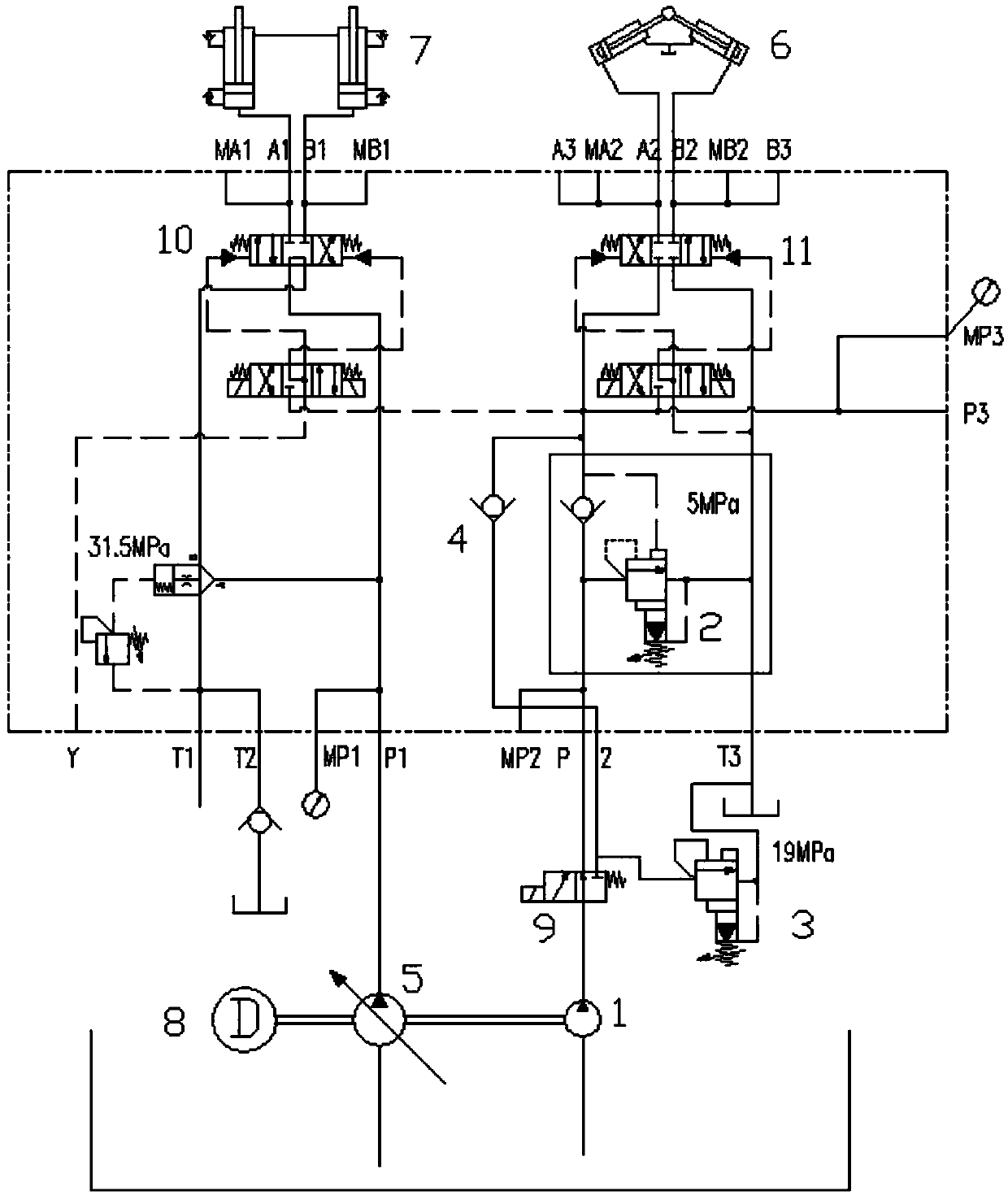
[0021] The swing cylinder gear pump 1 is connected with an electromagnetic reversing valve 9, and the electromagnetic reversing valve 9 is upwardly connected with a low-pressure relief valve 2, and the upper end of the low-pressure relief valve 2 is connected with a second hydraulic control reversing valve 11. The top of the hydraulic control reversing valve 11 is connected with the swing oil cylinder 6. When the electromagnetic reversing valve 9 is normally open, the oil pumped by the swinging cylinder gear pump 1 reaches the low pressure relief valve 2 through the electromagnetic reversing valve 9, and then passes through the second hydraulic control valve 9. The reversing valve 11 reaches the swing cylinder 6; the right end of the electromagnetic reversing valve 9 is connected with a high-pressure relief valve 3, and the high-press...


PUM


Abstract

The invention belongs to the technical field of pump truck fittings, and particularly relates to a novel oscillating cylinder hydraulic system of a boom pump truck and a concrete pump truck. A main body structure comprises an oscillating cylinder gear pump, a low-pressure overflow valve, a high-pressure overflow valve, a one-way valve, a plunger piston variable pump, an oscillating oil cylinder, apumping oil cylinder, an engine, an electromagnetic directional valve, a first hydraulic-control directional valve and a second hydraulic-control directional valve. Under different low-pressure and high-pressure working conditions, the novel oscillating cylinder hydraulic system regulates pipeline pressure through switching of a low-pressure overflow valve and a high-pressure overflow valve, eliminates impact, reduces noises of the whole truck, prolongs the service life of a cylinder pump valve, and improves reliability and stability of the whole system. The novel oscillating cylinder hydraulic system is simple in main body structure, is delicate in design and idea, is safe and convenient in use, effectively reduces use cost, is friendly in application effect, and is wide in market prospect.

Description

Technical field: [0001] The invention belongs to the technical field of pump truck accessories, and in particular relates to a novel boom pump truck swing cylinder hydraulic system and a concrete pump truck. Background technique: [0002] With the development of the economy and society, the construction industry has also made great progress, modern construction methods are constantly innovating, and the concrete boom pump truck is an important production tool in the construction industry, and the concrete boom pump truck for modern construction methods has a delivery capacity It has advantages such as large size and fast conveying speed, which play an irreplaceable role in speeding up the construction progress and reducing construction costs. At present, the focus of competition of foreign and domestically produced boom pump trucks is the technical level of the product, such as boom swing cylinder impact, noise, stability and service life. When pumping concrete, the concrete...

Claims


Application Information

Patent Timeline
IPC IPC(8): F15B11/16F15B13/06
CPCF15B11/16F15B13/06F15B2211/20546
Inventor 李绪省
Owner QINGDAO JIUHE HEAVY IND MACHINERY
Why Eureka
Try Eureka