Eureka AIR delivers breakthrough ideas for toughest innovation challenges, trusted by R&D personnel around the world.

Size deviation vicious circulation removing device for crane

A size deviation and vicious cycle technology, applied in the direction of cleaning methods and tools, cleaning methods using tools, cleaning methods using gas flow, etc., can solve the problem of increasing the power consumption of lifting dangerous lifting, accelerating the wear of the mating surface of parts, increasing Crane work costs and other issues

Inactive Publication Date: 2020-06-30
叶陈灿
View PDF0 Cites 1 Cited by
  • Summary
  • Abstract
  • Description
  • Claims
  • Application Information

AI Technical Summary

Problems solved by technology

[0003] Due to the working characteristics of the crane, its internal parts often wear and tear, and the metal debris that has fallen from the grinding is used as an abrasive to continue to participate in friction, which accelerates the wear of the mating surface of the parts. For this phenomenon, the prior art adopts damage The post-replacement processing method indirectly increases the working cost of the crane; in addition, when some objects need to be lifted, due to wind resistance and the weight of the objects, the objects will float in the air, and the floating objects will increase the danger of lifting and There is no corresponding processing mechanism in the prior art for the power consumption of hoisting, so a vicious cycle equipment for cranes to eliminate size deviations came into being

Method used


Image

  • Size deviation vicious circulation removing device for crane
  • Size deviation vicious circulation removing device for crane
  • Size deviation vicious circulation removing device for crane

Examples


Embodiment Construction

[0024] The following will clearly and completely describe the technical solutions in the embodiments of the present invention with reference to the accompanying drawings in the embodiments of the present invention. Obviously, the described embodiments are only some, not all, embodiments of the present invention. Based on the embodiments of the present invention, all other embodiments obtained by persons of ordinary skill in the art without making creative efforts belong to the protection scope of the present invention.

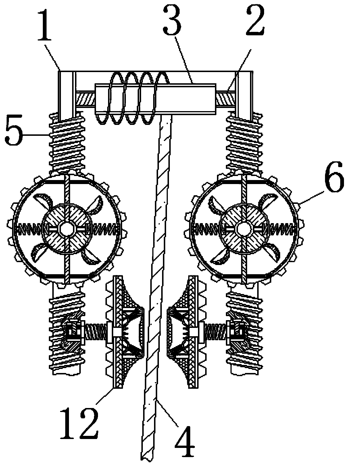
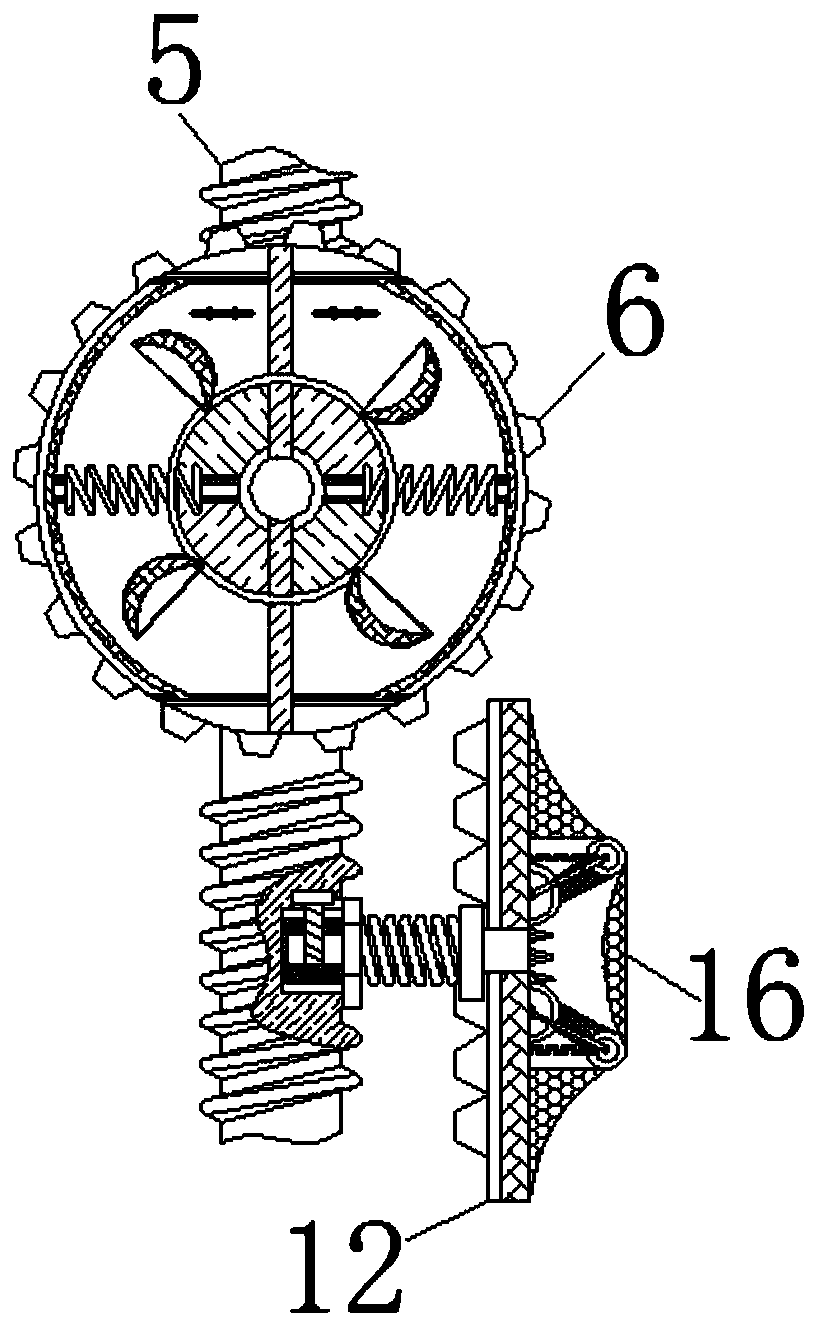
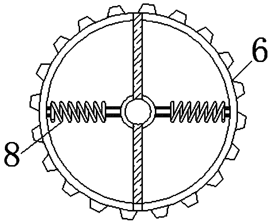
[0025] see Figure 1-8 , a vicious cycle equipment for cranes to eliminate size deviation, including a housing 1, the inside of the housing 1 is movably connected with a screw 2, and when the screw 2 rotates, it will mesh with the worm 5 to rotate, so the rotation speed of the two is the same, as The gear 11 restricts the swing of the steel rope 4 as a bedding, the surface of the screw 2 is movably connected with the bobbin 3, the surface of the spool 3 is wou...


PUM


Abstract

The invention relates to the technical field of crane daily use maintaining, and discloses a size deviation vicious circulation removing device for a crane. The device comprises a shell, a screw is movably connected into the shell, the surface of the screw is movably connected with a spool, the surface of the spool is wound with a steel rope, the two ends of the screw are movably connected with worms, gears are movably connected to the surfaces of the worms, fan impellers are movably connected into the gears, the surfaces of the fan impellers are movably connected with spring rods, the positions, located below the gears, of the surfaces of the worms are movably connected with engaging shafts, the right sides of the engaging shafts are movably connected with stretching springs, the sides, away from the engaging shafts, of the stretching springs are movably connected with tooth plates, the surfaces of the tooth plates are movably connected with holding plates, pressure exerted to the surfaces of the holding plates by the steel rope is continuously increased, when the tooth plates and the gears are in contact engaging, the tooth plates move upwards together with the steel rope, and therefore during object lifting, the steel rope is held, so that the object is prevented from falling off due to the too large swing amplitude.

Description

technical field [0001] The invention relates to the technical field of daily use and maintenance of cranes, in particular to a vicious circle equipment for eliminating size deviations of cranes. Background technique [0002] A crane refers to a multi-action hoisting machine that lifts vertically and carries heavy objects horizontally within a certain range. Also known as crane, aerial crane, crane; the main features are: the driving cab and the lifting control room are combined into one, which is evolved from a crawler crane, and the crawler and walking bracket parts of the walking mechanism are turned into tires. The chassis overcomes the disadvantage that the crawler shoes of crawler cranes cause damage to the road surface, and belongs to the material handling machinery. [0003] Due to the working characteristics of the crane, its internal parts often wear and tear, and the metal debris that has fallen from the grinding is used as an abrasive to continue to participate i...

Claims


Application Information

Patent Timeline
IPC IPC(8): B66C13/06B08B1/02B08B5/02
CPCB66C13/06B08B5/02B08B1/20
Inventor 叶陈灿
Owner 叶陈灿
Why Eureka
Eureka Blog
Learn More