
Surface-enhanced Raman scattering substrate and preparation method thereof

A surface-enhanced Raman, substrate technology, applied in the field of detection, can solve the problems of neglect, strong coupling interaction force confusion, etc.

Pending Publication Date: 2020-06-26
JIANGSU UNIV
View PDF1 Cites 7 Cited by
  • Summary
  • Abstract
  • Description
  • Claims
  • Application Information

AI Technical Summary

Problems solved by technology

[0003] However, most of the existing studies regard layered or film-like metal nanoparticles as a whole macroscopically, which will confuse the effect brought by a single metal particle with the strong coupling interaction between metal particles
Moreover, existing studies have ignored the influence of the polarization angle of the excitation light on the SERS enhancement effect of metal nanoparticles combined with two-dimensional materials.

Method used


Image

  • Surface-enhanced Raman scattering substrate and preparation method thereof
  • Surface-enhanced Raman scattering substrate and preparation method thereof
  • Surface-enhanced Raman scattering substrate and preparation method thereof

Examples


Embodiment 1

[0027] A method for preparing a silver nanowire / molybdenum disulfide composite material surface-enhanced Raman scattering substrate, comprising the following steps:

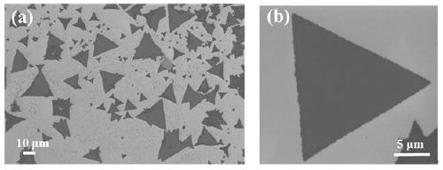
[0028] (1) Chemical vapor deposition (CVD) growth of molybdenum disulfide nanosheets: place sulfur powder with a purity of 99.5% in a quartz boat and connect it with a self-made push rod, and place it in the first horizontal tube furnace. At the front end of the heating zone, place molybdenum trioxide powder with a purity of 99.99% in another quartz boat, which is placed in the center of the second heating zone of the horizontal tube furnace, and the distance between the sulfur source and the molybdenum source is 10cm. The silicon growth substrate covered with a 285nm silicon dioxide layer was ultrasonically cleaned with acetone, ethanol, and deionized water, respectively, and then dried and placed upside down on the top of the second quartz boat. Use a vacuum pump to evacuate the horizontal tube furnace to 100 m...

Embodiment 2

[0037] Step (1) to step (3) are the same as in Example 1,

[0038] (4) Raman measurement: 10 μL was dropped on the surface of the composite material obtained in step (3) with a concentration of 10 -6 The mol / L rhodamine 6G solution was tested by Raman spectroscopy on silver nanowires / molybdenum disulfide at a light polarization angle of 45°; the laser parameters were set as follows: the laser spot is 2μm, the wavelength is 532nm, and the power is 5mW.

Embodiment 3

[0044] Step (1) to step (3) are the same as in Example 1,

[0045] (4) Raman measurement: 10 μL was dropped on the surface of the composite material obtained in step (3) with a concentration of 10 -6 The mol / L rhodamine 6G solution was tested by Raman spectroscopy on silver nanowires / molybdenum disulfide at a light polarization angle of 90°; the laser parameters were set as follows: the laser spot is 2μm, the wavelength is 532nm, and the power is 5mW.


PUM

PropertyMeasurementUnit
Concentrationaaaaaaaaaa

Abstract

The invention discloses a silver nanowire / molybdenum disulfide composite material surface enhanced Raman scattering substrate and a preparation method thereof, belongs to the technical field of detection, and is characterized in that the substrate is of a layered structure and sequentially comprises a silicon layer, a silicon dioxide layer, a triangular MoS2 layer and a metal silver nano-wire layer from bottom to top; the triangular MoS2 layer grows on the silicon dioxide layer through a chemical vapor deposition method, and the metal silver nano-wire layer is directly deposited on the triangular MoS2 layer. According to the surface-enhanced Raman scattering substrate, the silver nanowires are coupled to the molybdenum disulfide nanosheets to form a composite material, then Raman testing is conducted, and the SERS signal strength is improved from the aspect of electromagnetic enhancement through enhancement of a hot spot electric field at the interface between molybdenum disulfide andthe silver nanowires. The SERS substrate material is high in preparation repeatability and simple in step operation.

Description

technical field [0001] The invention belongs to the technical field of detection, and in particular relates to a surface-enhanced Raman scattering substrate and a preparation method. Background technique [0002] Surface-enhanced Raman scattering (SERS) is an analytical technique that detects analytes based on different molecular vibration levels and structural information. This technology overcomes the shortcomings of low sensitivity of Raman spectroscopy, has the advantages of high sensitivity, strong specificity, in-situ non-destructive testing, etc., and is widely used in physics, chemistry, biology and other fields. Noble metals such as gold, silver, and copper have good plasmonic enhancement effects, and are commonly used SERS substrate materials. It has always been a challenging research topic to select a suitable support body and construct a suitable substrate material structure to improve the sensitivity, stability and uniformity of SERS detection. At present, sci...

Claims


Application Information

Patent Timeline
IPC IPC(8): G01N21/65B82Y30/00C23C16/30
CPCG01N21/658C23C16/305B82Y30/00
Inventor 于露露张钰徐健吕柳
Owner JIANGSU UNIV
Learn More