
Combined technique for producing high-end graphite carbon material

A kind of graphite carbon, high-end technology, applied in the field of combination process of high-end graphite carbon materials, can solve problems such as large performance gap and unfavorable industrial applications

Pending Publication Date: 2020-06-23
CHINA PETROLEUM & CHEM CORP +1
View PDF10 Cites 1 Cited by
  • Summary
  • Abstract
  • Description
  • Claims
  • Application Information

AI Technical Summary

Problems solved by technology

Therefore, for the traditional delayed coking process, there are generally large gaps in the performance of high-end graphite carbon materials in different coke towers or different production batches of the same coke tower, which is not conducive to industrial applications. How to prepare high-quality high-end graphite with uniform performance Carbon material products have always been the goal pursued by R&D personnel

Method used


Image

  • Combined technique for producing high-end graphite carbon material
  • Combined technique for producing high-end graphite carbon material
  • Combined technique for producing high-end graphite carbon material

Examples


Embodiment 1

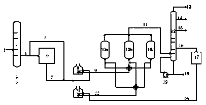
[0087] Catalytic oil slurry from a certain refinery is used as raw material. See Table 1 for the analysis of the specific properties of the oil slurry. The raw material inlet temperature of the vacuum deep-drawing tower is 375°C, the temperature at the top of the tower is 80°C, the absolute pressure at the top of the tower is 20mmHg, and the temperature at the bottom of the tower is The temperature is 400°C; the catalyst for hydrotreating unit adopts CEN, FZC, ZTN, ZTS series residual oil hydrogenation catalyst produced by Sinopec Catalyst Branch Company, including protective agent, demetallization catalyst, desulfurization catalyst and denitrogenation catalyst etc., the loading sequence is generally to make the raw material oil contact with the protective agent, hydrodemetallization, hydrodesulfurization, and hydrodenitrogenation catalysts in sequence. Of course, there is also a technology of mixing and loading these catalysts. The above-mentioned catalyst loading technology i...

Embodiment 2

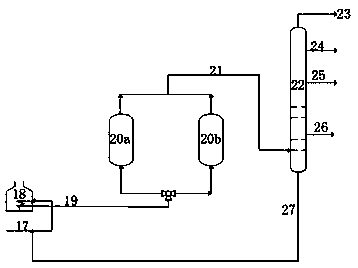
[0098] Using the same device and raw material as in Example 1, the same vacuum deep drawing and hydrotreating process conditions, the coking raw material is hydrotreated oil and vacuum deep drawing light distillate mixed oil, the mixing ratio is 1:1, and the coking tower The top pressure is 0.6MPa, and the coking cycle of coking is 36h. According to the operation of the three-tower switching method provided by the present invention, when the coke charging time of the oil slurry coke tower accounts for 50% of the total coke charging time, switch to coking light wax oil and continue Charging, wherein, in step (1), the outlet temperature of heating furnace 1 is 420°C-450°C heating-constant temperature process, the heating rate is 5°C / h, the constant temperature time is 12h, and the gas velocity in the coke tower is controlled at 0.05-0.08m / s, the outlet temperature of the heating furnace 2 in step (2) is 470°C-490°C heating-constant temperature process, the heating rate is 10°C / h...


PUM


Abstract

The invention discloses a combined technique for producing a high-end graphite carbon material. The method comprises the following steps: fractionating raw oil to obtain heavy distillate oil and lightdistillate oil; discharging the heavy distillate oil from the device (or discharging a part of the heavy distillate oil from the device and circulating a part of the heavy distillate oil to the bottom of a fractionating tower), introducing a part of the light distillate oil into a hydrotreating device, carrying out a hydrotreating reaction in the presence of hydrogen and a hydrogenation catalyst,mixing the hydrotreated material with residual light distillate oil after hydrotreating, serving the mixture as a coking raw material (also called as a green coke raw material); and feeding the coking raw material into a coking device, and carrying out reactions to obtain the high-end graphite carbon material. The method can be used for continuously producing the high-quality high-end graphite carbon material with a stable performance.

Description

technical field [0001] The invention relates to a combined process method for producing high-end graphite carbon materials, in particular to a combined process method for continuously producing high-end graphite carbon materials with stable performance. Background technique [0002] Needle coke is mainly used to produce high-power and ultra-high-power graphite electrodes. With the development of the steel age, the output of steel scrap has gradually increased, which has promoted the development of electric furnace steel, and will inevitably increase the amount of graphite electrodes, especially high-power and ultra-high-power electrodes, and the demand for needle coke will also continue to increase. [0003] CN200810017110.3 discloses a method for preparing needle coke. The fraction or residual oil rich in aromatics is subjected to a delayed coking treatment with a certain temperature rise program, and then the obtained green coke is calcined to obtain a needle-shaped coke w...

Claims


Application Information

Patent Timeline
IPC IPC(8): C01B32/205C10G67/02
CPCC01B32/205C10G67/02
Inventor 赵日峰方向晨初人庆郭丹宋永一刘继华勾连忠武云
Owner CHINA PETROLEUM & CHEM CORP
Learn More