Countercurrent suspension type oven

A suspension type, oven technology, applied in the direction of printing, printing machines, general parts of printing machinery, etc., can solve the problems of extraction, low drying efficiency, large overprinting error, etc., to ensure overprinting accuracy and improve drying efficiency Effect

Pending Publication Date: 2020-06-23
青岛成盛林环保设备有限公司
View PDF0 Cites 4 Cited by
  • Summary
  • Abstract
  • Description
  • Claims
  • Application Information

AI Technical Summary

Problems solved by technology

[0002] The existing gravure printing machine oven is a traditional single-sided air blowing old-fashioned oven, which has many defects: First, it is a single-sided direct blowing oven with an air shovel, and the air shovel and the printing film are blown at 90 degrees, and the blowing pipe is parallel to the exhaust pipe After being blocked by the printing film, the drying air disperses in two directions up and down, and part of it flows upwards following the printing film. Because it is at the same speed as the printing film, it is relatively static and does not generate mutual friction, so it is discharged without drying. Duct extraction
The drying air that flows downwards is in contact with the printing film and is sucked away by the exhaust pipe. Since the oven is always operating under a slight negative pressure, the contact area between the drying air and the printing film is small and the drying efficiency is low.
Second, the traditional oven is blown on one side, and the printing film shakes seriously, resulting in large overprint errors
Third, because the printing film is blown and dried on one side, the ink dries slowly and the efficiency is low, and anti-sticking often occurs

Method used


Image

  • Countercurrent suspension type oven
  • Countercurrent suspension type oven
  • Countercurrent suspension type oven

Examples


Embodiment Construction

[0023] Hereinafter, the construction principle of the present invention will be further described according to the above description and accompanying drawings.

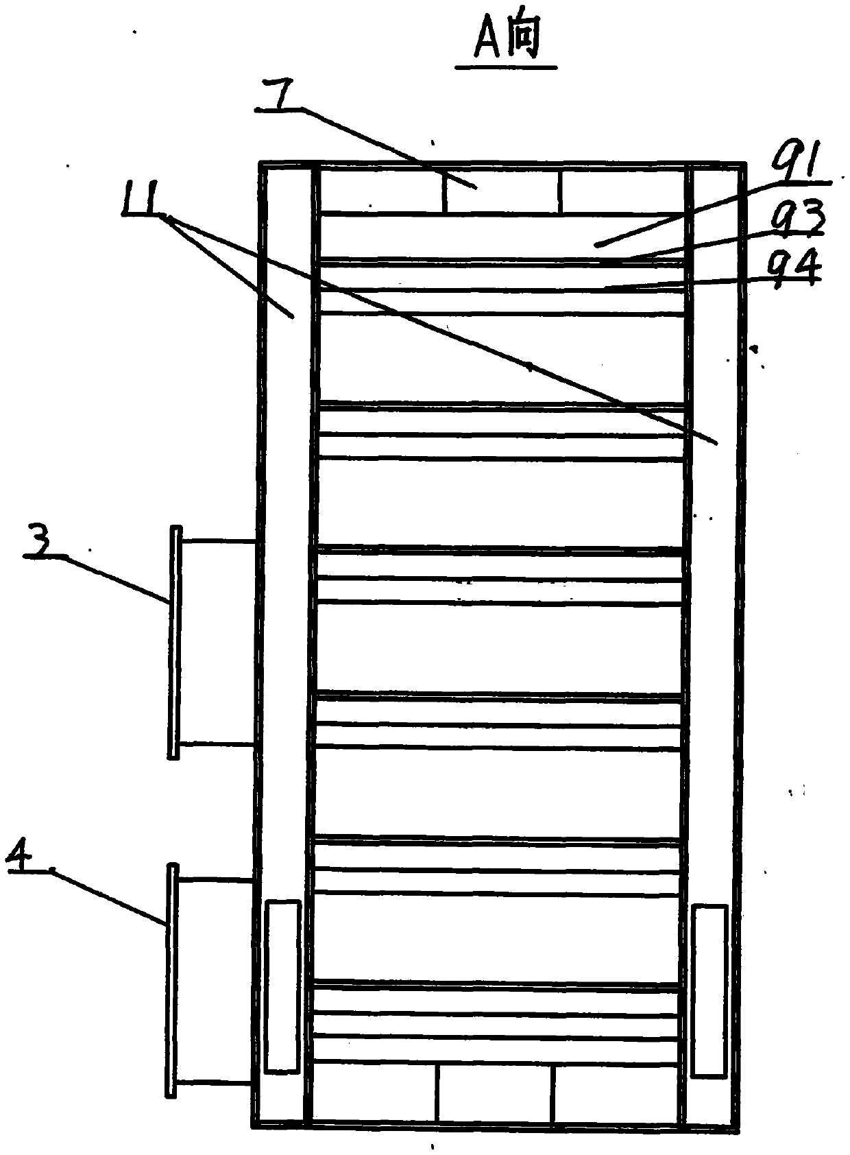
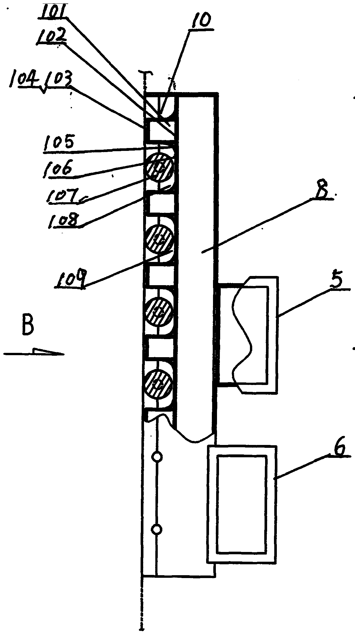
[0024] The countercurrent suspension oven includes two parts, the left half oven 1 and the right half oven 2, which are relatively closed together during operation, and the printing film 20 passes through the gap between the left and right half ovens.

[0025] The structure of the left half oven 1 includes, from the outside to the inside, the first main air inlet pipe 3 and the first main exhaust pipe 4 arranged horizontally, the first middle air inlet pipe 7 arranged vertically and its two sides The first row of air ducts 11, and the blowing ducts 91, wind shovels 93, wind deflectors 94 and exhaust gas guide pipes 95 arranged horizontally and connected to each other. The two ends of the waste gas guide pipe are respectively plugged with the first exhaust pipes 11 on both sides. The air inlet 92 at the top of the blo...


PUM


Abstract

The invention discloses a countercurrent suspension type oven, relates to printing equipment and coating machine and laminating machine equipment, and mainly relates to a countercurrent suspension type oven of a photogravure press. The countercurrent suspension type oven comprises two parts including a left half oven and a right half oven, wherein the left half oven and the right half oven are integrally folded relatively during operation, and a printing film passes through a gap between the two half ovens; the left half oven structurally comprises a main air inlet pipe and a main exhaust pipe, a middle air inlet pipe and two side exhaust pipes are arranged inside, and a blowpipe air chipper, an air deflector and an exhaust gas diversion pipe which are engaged to each other are arranged inthe innermost position; and the right half oven structurally comprises a main air inlet pipe and a main exhaust pipe, a middle air inlet pipe and two side exhaust pipes are arranged inside, and a suspension air pipe, a top suspension support plate and an air nozzle which are engaged to each other are arranged in the innermost position. The countercurrent suspension type oven has the beneficial effects that the printing film is in suspension and cannot shake under the combined action of the air chipper and the air deflector of the left half oven as well as the suspension air pipe and the suspension support plate of the right half oven, so that the overprint of the press is accurate, and the front and back sides of the printing film are blown at the same time, so that the drying efficiencyis greatly improved.

Description

Technical field: [0001] The present invention relates to printing technology equipment, coating machine and composite machine equipment, mainly relates to gravure printing machine, especially relates to the countercurrent suspension oven of gravure printing machine. Background technique: [0002] The existing gravure printing machine oven is a traditional single-sided air blowing old-fashioned oven, which has many defects: First, it is a single-sided direct blowing oven with an air shovel, and the air shovel and the printing film are blown at 90 degrees, and the blowing pipe is parallel to the exhaust pipe After being blocked by the printing film, the drying air disperses in two directions up and down, and part of it flows upwards following the printing film. Because it is at the same speed as the printing film, it is relatively static and does not generate mutual friction, so it is discharged without drying. The air duct is removed. The drying air flowing downwards contact...

Claims


Application Information

Patent Timeline
Patent Type & Authority Applications(China)
IPC IPC(8): B41F23/04
CPCB41F23/0426
Inventor 隋林波
Owner 青岛成盛林环保设备有限公司
Why Eureka
Try Eureka