A Transformer Winding Arrangement Method and Its Displacement Current Numerical Analysis Method

A transformer winding and displacement current technology, applied in the field of transformers, to eliminate common mode noise, simplify the difficulty of noise elimination, and improve EMI performance

Active Publication Date: 2021-08-17
连云港杰瑞电子有限公司 +1
View PDF11 Cites 0 Cited by
  • Summary
  • Abstract
  • Description
  • Claims
  • Application Information

AI Technical Summary

Problems solved by technology

[0004] The purpose of the present invention is to propose a transformer winding arrangement method and its displacement current numerical analysis method in order to overcome the deficiencies in the prior art, optimize the design of the transformer winding arrangement, and build a numerical analysis model of the displacement current. By optimizing the winding The parameter design makes the displacement current of common mode noise zero, realizes the elimination of common mode noise without using Y-type wiring capacitors, and improves the electromagnetic interference performance of the transformer

Method used


Image

  • A Transformer Winding Arrangement Method and Its Displacement Current Numerical Analysis Method
  • A Transformer Winding Arrangement Method and Its Displacement Current Numerical Analysis Method
  • A Transformer Winding Arrangement Method and Its Displacement Current Numerical Analysis Method

Examples


Embodiment 1

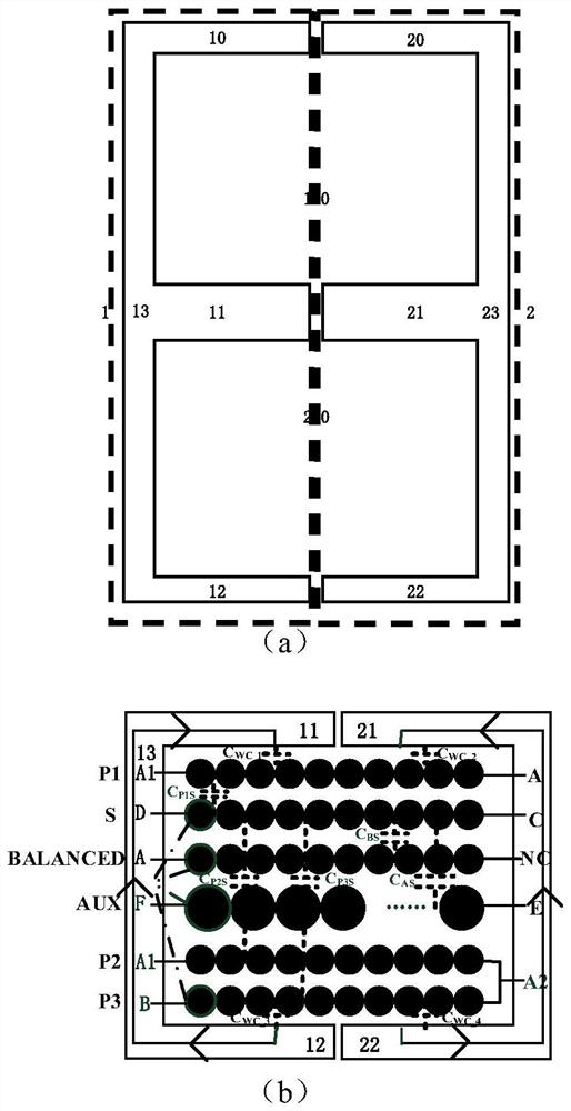
[0030] Example 1. In a transformer winding arrangement method and its displacement current numerical analysis method proposed by the present invention, the transformer winding arrangement is as follows figure 1 shown, figure 1 (a) is a schematic diagram of the magnetic core structure of the transformer. The magnetic core structure includes: a left magnetic core 1 and a right magnetic core 2 . The left magnetic core 1 and the right magnetic core 2 are both E-type magnetic cores. The left magnetic core 1 includes: the left magnetic core upper column 10, the left magnetic core center column 11, the left magnetic core lower column 12, the left magnetic core column 13; the right magnetic core 2 includes: the right magnetic core upper The column 20 , the center column 21 of the right magnetic core, the lower column 22 of the right magnetic core, and the upright column 23 of the right magnetic core. The left magnetic core 1 and the right magnetic core 2 constitute the upper magnet...

Embodiment 2

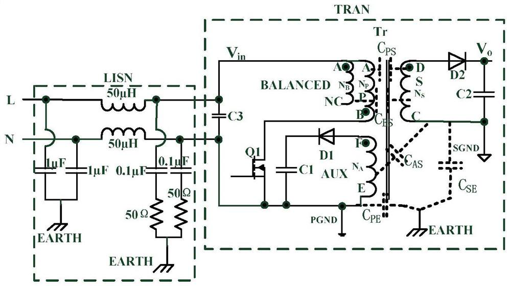
[0040] Example 2. In a preferred embodiment, the transformer structure proposed by the present invention is applied to a flyback converter, and the topology of the flyback converter used is as follows figure 2 shown.

[0041] The topology of the flyback converter includes: a linear impedance stabilization network part LISN and a converter part TRAN.

[0042] The converter part TRAN includes: Transformer T r , the primary side main power tube Q1, the first diode D1, the second diode D2, the first output filter capacitor C1, the second output filter capacitor C2, and the third capacitor C3. Among them, the transformer Tr includes: the primary winding P, the secondary winding S, the balance winding BALANCED, and the auxiliary winding AUX.

[0043] The L end of the linear impedance stabilization network LISN is connected to one end of the third capacitor C3, and the N end is connected to the other end of the third capacitor C3.

[0044] The A end of the primary winding P of t...

Embodiment 3

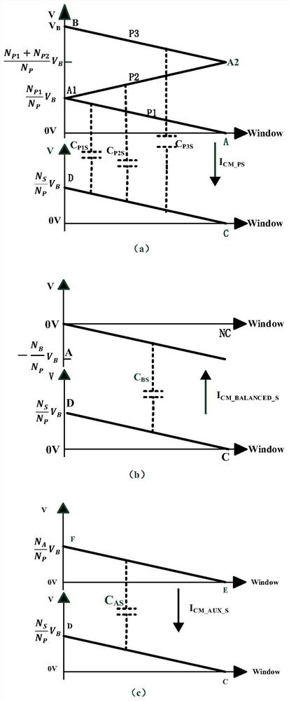
[0048] Example 3. When the flyback converter is working, under the arrangement of the transformer windings proposed by the present invention, the potential change and the displacement current distribution between each winding located at the primary position and the secondary winding S are as follows: image 3 shown. exist image 3 , the abscissas of each potential change and displacement current distribution diagram represent the first primary winding P1, the second primary winding P2, the third primary winding P3, the secondary winding S, the auxiliary winding AUX and the balance on the same layer. The distance between each turn of the winding BALANCED and the left magnetic core column 13, where the starting point of the abscissa represents the closest turn of each winding to the left magnetic core column 13, so the starting point of the abscissa is defined as the leftmost side of the magnetic core window; The coordinates take 0V as the starting point, indicating the magnit...


PUM


Abstract

The invention provides a transformer winding arrangement method and a displacement current numerical analysis method thereof, which relate to the technical field of transformers. The present invention optimizes the arrangement of each winding of the transformer and divides the primary winding into the first primary winding, the second primary winding and the third primary winding. According to the direction from the central column of the magnetic core to the side column of the magnetic core, the transformer winding The order of arrangement is: the first primary winding, the secondary winding, the balance winding, the auxiliary winding, the second primary winding, and the third primary winding; the numerical analysis model of the displacement current is also constructed, and the winding parameter design is optimized so that the generated Common mode noise has zero displacement current. The invention simultaneously reduces the common-mode noise from both the noise source and the noise path, realizes the elimination of the common-mode noise without using a Y-shaped connection capacitor, and optimizes the EMI performance of the transformer.

Description

technical field [0001] The invention relates to the technical field of transformers, in particular to a method for arranging transformer windings and a method for numerical analysis of displacement current. Background technique [0002] In the application of low power converters, the flyback converter is one of the most widely used topologies. Its topology causes a large dv / dt when the primary side power tube and the secondary side rectifier tube are suddenly turned off. Due to the existence of a lot of parasitic capacitance between the windings and between the windings and the ground, the generated current flows between the power line and the ground. A loop is formed between them, thus causing a lot of common mode noise. Usually, a Y-type wiring capacitor is connected between the primary side ground and the secondary side ground to effectively suppress common mode noise. However, this method will lead to increased leakage current, so there are potential safety hazards in m...

Claims


Application Information

Patent Timeline
Patent Type & Authority Patents(China)
IPC IPC(8): H01F27/28H01F27/30H01F27/34H01F27/38H01F27/33G06F30/20H02M1/44G06F111/10
CPCH01F27/28H01F27/306H01F27/33H01F27/34H01F27/38H02M1/44
Inventor 唐海瑞朱赛娟王廷营王永生许胜有孙伟锋钱钦松孙娟顾亮邰阳
Owner 连云港杰瑞电子有限公司
Why Eureka
Try Eureka