Eureka AIR delivers breakthrough ideas for toughest innovation challenges, trusted by R&D personnel around the world.

Trench manufacturing method

A manufacturing method and trench technology, applied in semiconductor/solid-state device manufacturing, electrical components, circuits, etc., can solve the problems of etching or etching stop, etching trench bridging defect photoresist residue, etc.

Active Publication Date: 2020-06-16
WUHAN XINXIN SEMICON MFG CO LTD
View PDF7 Cites 0 Cited by
  • Summary
  • Abstract
  • Description
  • Claims
  • Application Information

AI Technical Summary

Problems solved by technology

[0003] The purpose of the present invention is to provide a method for making trenches to solve the partial etching or etching stop of the trench caused by polymer accumulation in the existing etched trench, and the bridging defects that are prone to occur in the etched trench and photoresist remaining at the bottom of the trench

Method used


Image

  • Trench manufacturing method
  • Trench manufacturing method
  • Trench manufacturing method

Examples


Embodiment Construction

[0026] The groove manufacturing method proposed by the present invention will be further described in detail below in conjunction with the accompanying drawings and specific embodiments. Advantages and features of the present invention will be apparent from the following description and claims. It should be noted that all the drawings are in a very simplified form and use imprecise scales, and are only used to facilitate and clearly assist the purpose of illustrating the embodiments of the present invention.

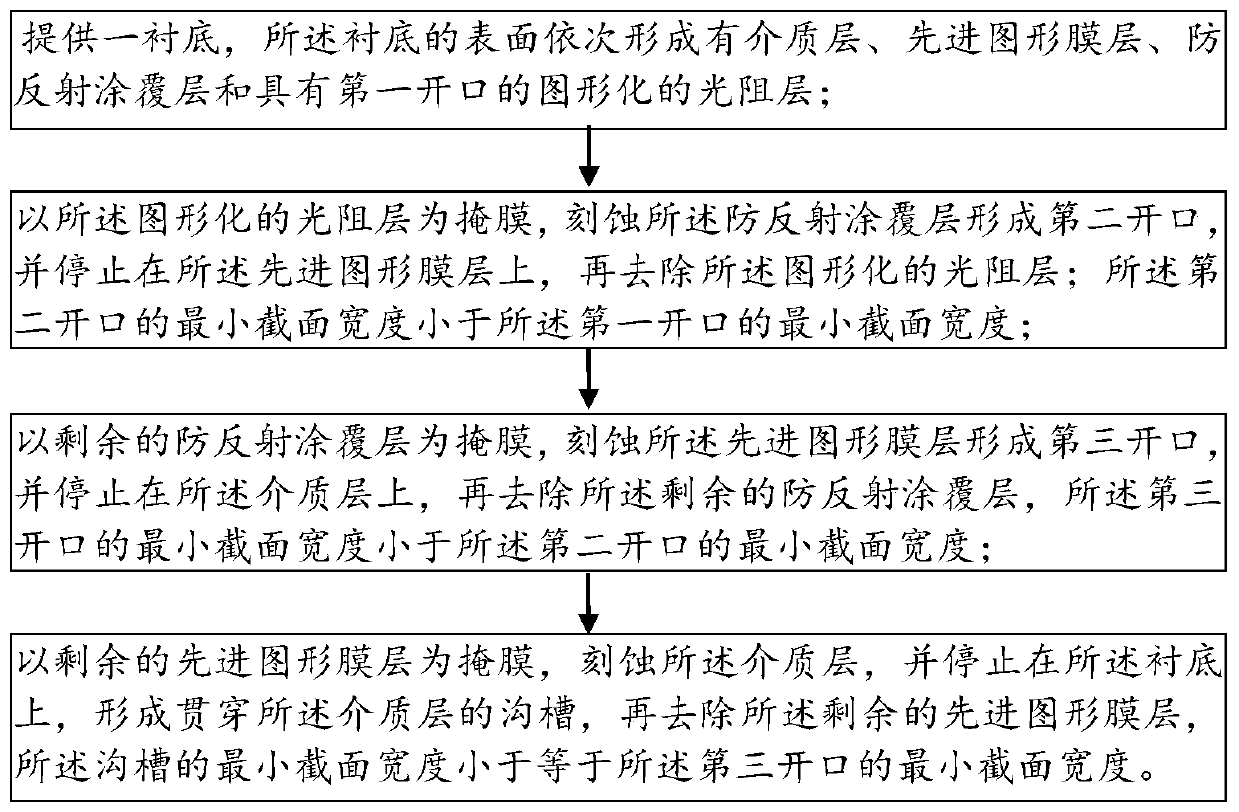
[0027] A trench making method such as figure 1 Shown include:

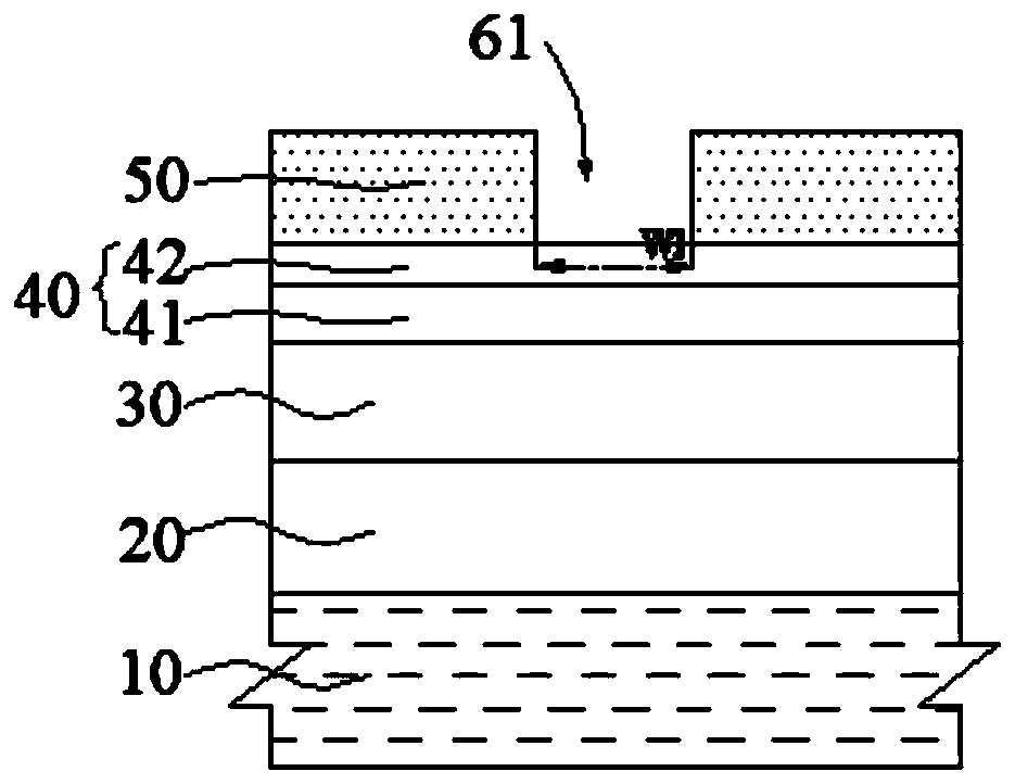
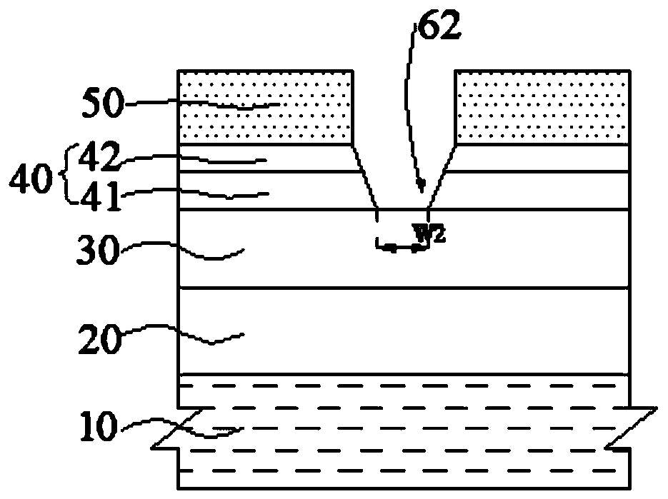
[0028] A substrate is provided, the surface of the substrate is sequentially formed with a dielectric layer, an advanced graphics film layer, an anti-reflection coating layer and a patterned photoresist layer with a first opening;

[0029] Using the patterned photoresist layer as a mask, etching the antireflection coating layer to form a second opening, and stopping on the advanced graphics film layer, and...


PUM


Abstract

The invention provides a trench manufacturing method. The method comprises the steps that: a substrate is provided, and a dielectric layer, an advanced pattern film layer, an anti-reflection coating layer and a patterned photoresist layer with a first opening are sequentially formed on the surface of the substrate; the anti-reflection coating layer is etched with the patterned photoresist layer adopted as a mask, so that a second opening can be formed; with the residual anti-reflection coating layer adopted as a mask, the advanced pattern film layer is etched, so that a third opening can be formed, and the residual anti-reflection coating layer is removed; and the dielectric layer is etched with the residual advanced pattern film layer adopted as a mask, so that a trench penetrating through the dielectric layer can be formed. The layers are etched one by one in sequence; the previous masks are removed one by one; and the layers are narrowed by one by one; and therefore, the groove witha high depth-to-width ratio can be formed, and the photoresist can be prevented from being left at the bottom of the trench. The advanced pattern film layer is used as the mask to well control a bridging defect, so that a pattern transfer capability is more reliable and stable, the physical morphology of the trench is well controlled, and the stop of an etching process and the accumulation of polymers are effectively controlled.

Description

technical field [0001] The invention relates to the technical field of integrated circuits, in particular to a trench manufacturing method. Background technique [0002] Trenches with high aspect ratios are widely used in 3D integrated circuits (3DICs), such as trenches for realizing metal interconnections. When etching to form a trench with a high aspect ratio, the etching gas is usually etched downward to form the trench, and at the same time, the polymer gas is injected to form a polymer on the sidewall of the trench to reduce the chemical corrosion of the sidewall of the trench. During etching, as the polymer previously formed on the sidewall, under the influence of ions colliding with the sidewall, the detached sidewall moves again and reattaches on the deeper sidewall. In this way, the polymer on the sidewall is continuously driven downward and attached, so that it is easy for polymer accumulation to cause partial etching or etching stop of the trench with high aspect...

Claims


Application Information

Patent Timeline
IPC IPC(8): H01L21/768
CPCH01L21/76802
Inventor 宋保英谢岩
Owner WUHAN XINXIN SEMICON MFG CO LTD
Why Eureka
Eureka Blog
Learn More