


Quick Research
Generate reliable direction feasibility study reports for your R&D in just a few steps.

Technical Q&A
Discover and master advanced knowledge NOW. Basics, ideas, possibilities, all at once.

Find Solutions
As an expert in R&D theories, this can generate solutions to your technical problems instantly.

Evaluate Feasibility
Analyze your overall solution with one click, know your potential R&D risks in advance.

Monitor Landscape
Get weekly tech updates, stay abreast of the latest tech innovations and key insights.
Lithium battery quick charging circuit and application thereof
A technology of lithium batteries and battery packs, applied in battery circuit devices, different battery charging, circuit devices, etc., can solve the problems of high cost, cumbersome design of constant voltage and constant current chargers, etc., and achieve the effect of improving cost performance
- Summary
- Abstract
- Description
- Claims
- Application Information
AI Technical Summary
Problems solved by technology
Method used
Image

Examples
Embodiment 1
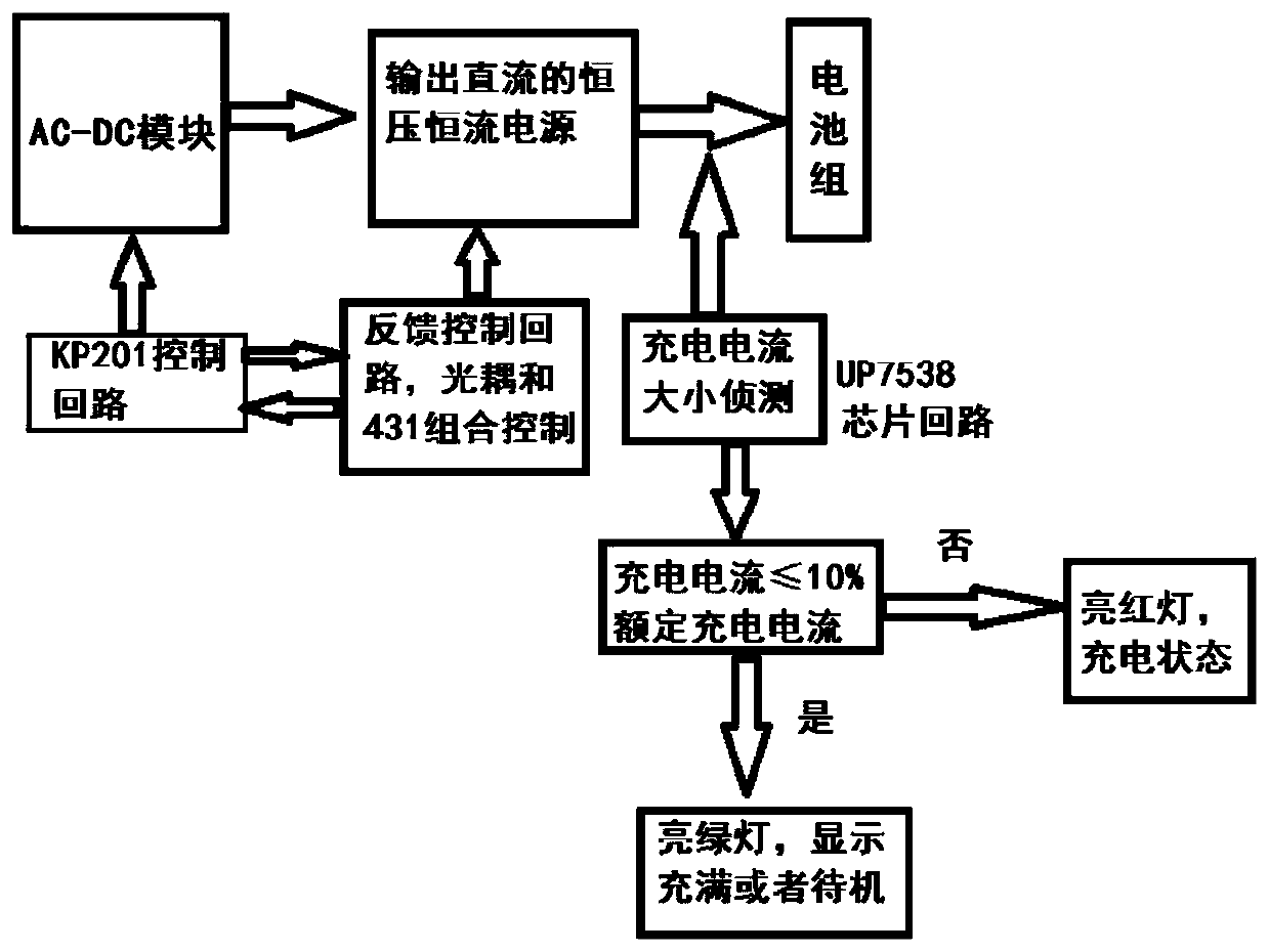
[0030] see Figure 2 to Figure 6 As shown, this embodiment provides a lithium battery fast charging circuit, including a C-DC switching power supply module, an indicator light indicating control module, and a constant voltage and constant current feedback control loop.
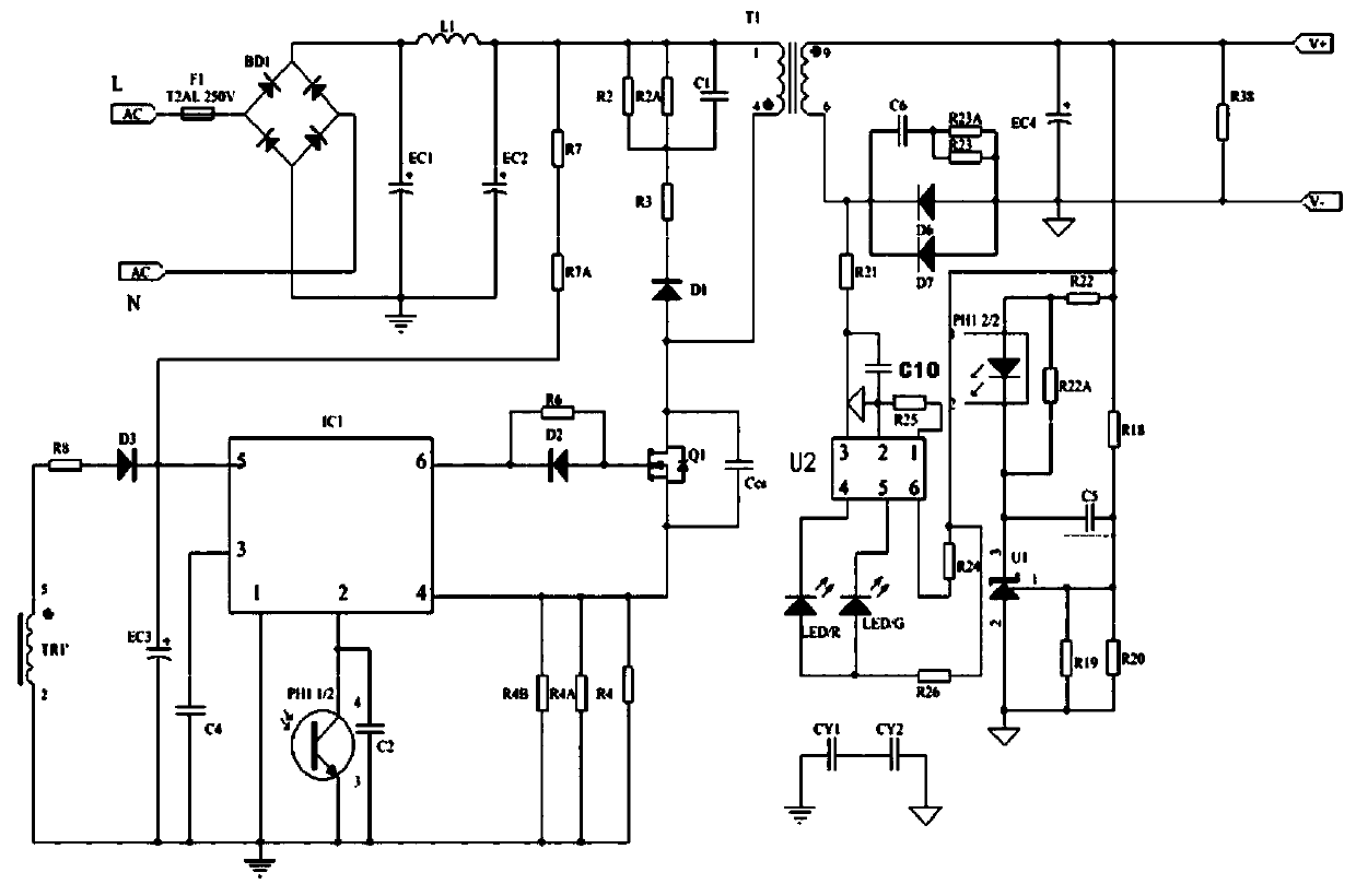
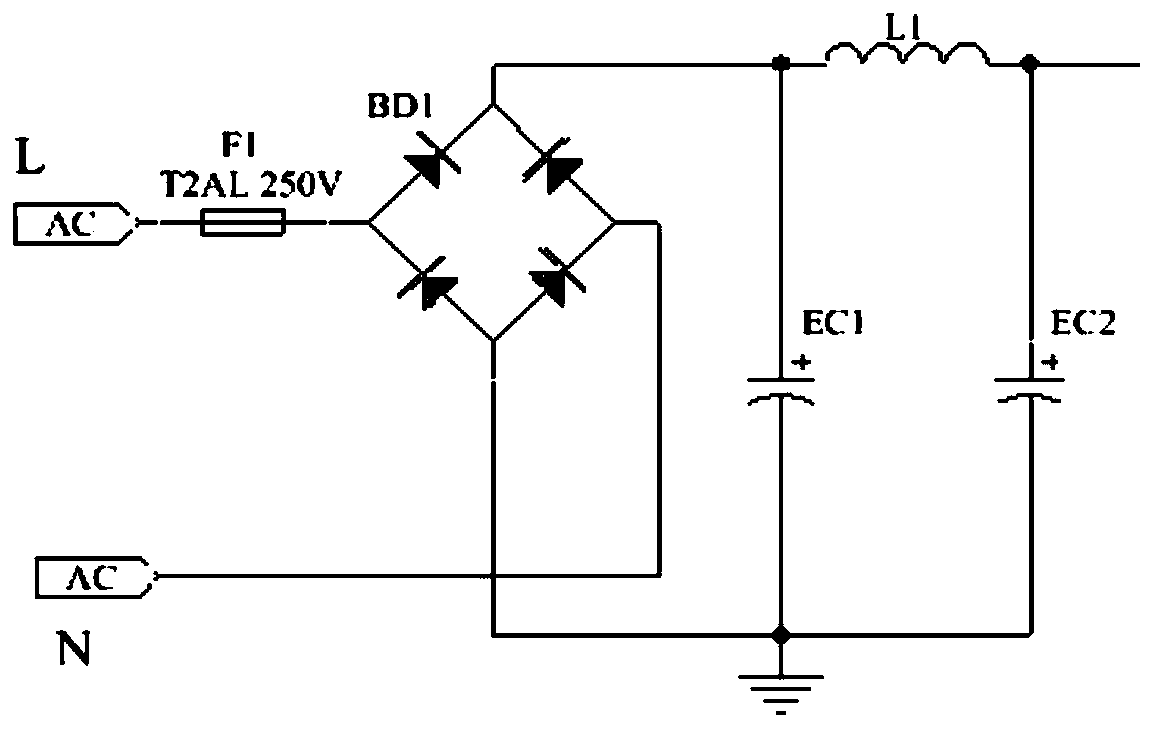
[0031] like figure 2 and image 3 As shown, the AC-DC switching power supply module has two mains input terminals L, N, and is connected to two battery pack connection terminals V+ and V-; further includes: fuse F1, rectifier bridge BD1, and EC1, EC2, The filtering and EMC circuit composed of L1; BD1 is a fast recovery rectifier bridge, which refers to a rectifier bridge with a reverse recovery time ≤ 50nS. BD1 is a combination of 4 diodes (such as FR, HER series), with Four pins A1, A3, B3 and C4, among them, the A1 pin of BD1 is connected to the mains input terminal L through the fuse F1, the A3 pin is connected to the mains input terminal N, the B3 pin is connected to the primary coil of T1 through L1, a...
Embodiment 2
[0045] This embodiment is an application of the lithium battery fast charging circuit in the first embodiment to an electric tool, which can be used for fast charging of the electric tool. Its typical parameters are 12V2.4A for three strings of 18650 power batteries with a capacity of 2000mA, which can be charged within one hour.
[0046] The advantage of the present invention is that: the lithium battery fast charging circuit of the present invention adopts a chip (such as a KP201 chip or a DP2291 chip) that requires secondary side control and can realize constant voltage and constant current functions to perform secondary side control constant voltage and constant current output, and adopts The chip that can detect the voltage of the secondary rectifier diode (such as the UP7358 chip) realizes the charging indication circuit, so as to form a constant voltage constant current charger with an indicator light. This solution saves the cumbersome design of LM358 and high-power sam...
PUM
 Abstract
Description
Claims
Application Information
 - R&D Engineer
- R&D Manager
- IP Professional
- Industry Leading Data Capabilities
- Powerful AI technology
- Patent DNA Extraction
Browse by: Latest US Patents, China's latest patents, Technical Efficacy Thesaurus, Application Domain, Technology Topic, Popular Technical Reports.
© 2024 PatSnap. All rights reserved.Legal|Privacy policy|Modern Slavery Act Transparency Statement|Sitemap|About US| Contact US: help@patsnap.com