Differential band-pass frequency modulation MEMS gyroscope rate analysis device and method

A technology of analysis device and gyroscope, applied in measurement devices, instruments, etc., can solve problems such as electromagnetic interference, adverse effects of signal-to-noise ratio, and adverse system signal-to-noise ratio.

Active Publication Date: 2020-06-09
OCEAN UNIV OF CHINA
View PDF8 Cites 0 Cited by
  • Summary
  • Abstract
  • Description
  • Claims
  • Application Information

AI Technical Summary

Problems solved by technology

[0003] The above FM MEMS gyroscope rate analysis scheme has the following problems in practical application: 1. The main rate analysis links of the traditional scheme are all implemented in the analog circuit. Maintain accurate analysis in the environment
2. Traditional solutions mostly use common-mode signal acquisition. In the actual circuit operation process, common-mode signal acquisition will introduce the influence of common-mode noise signals, which is not conducive to the overall signal-to-noise ratio of the system.
3. The analog phase-locked loop circuit used in the traditional solution needs to introduce a high-speed crystal oscillator signal for multiple gyroscope output signals in the analog circuit area. Due to the high-speed switching characteristics of this signal, a large number of spikes will be added to the signal edge, which will cause A large amount of electromagnetic interference seriously affects the normal circulation of analog signals, which will undoubtedly have an adverse effect on the signal-to-noise ratio, and the butterfly switch mixer aggravates this problem
4. Due to the physical characteristics of the MEMS gyroscope, the analysis device needs to provide it with a DC signal to drive the start-up, which causes the DC bias to be superimposed on the output signal of the gyroscope. The traditional solution only uses low-pass filtering to filter out High-frequency noise signal, ignoring the impact of DC bias noise on the system, which in turn affects the signal-to-noise ratio of the device
5. The traditional solution uses an ordinary crystal oscillator, which is susceptible to errors due to the influence of ambient temperature
6. The traditional solution uses an analog low-pass filter before the resolution rate, which causes a phase delay problem. Only using a trigger with a strong synchronization signal may easily cause insufficient phase compensation
7. The low-pass filter of traditional I / Q demodulation cannot effectively filter out the superimposed high-order harmonic components in the demodulated signal

Method used


Image

  • Differential band-pass frequency modulation MEMS gyroscope rate analysis device and method
  • Differential band-pass frequency modulation MEMS gyroscope rate analysis device and method
  • Differential band-pass frequency modulation MEMS gyroscope rate analysis device and method

Examples


Embodiment 1

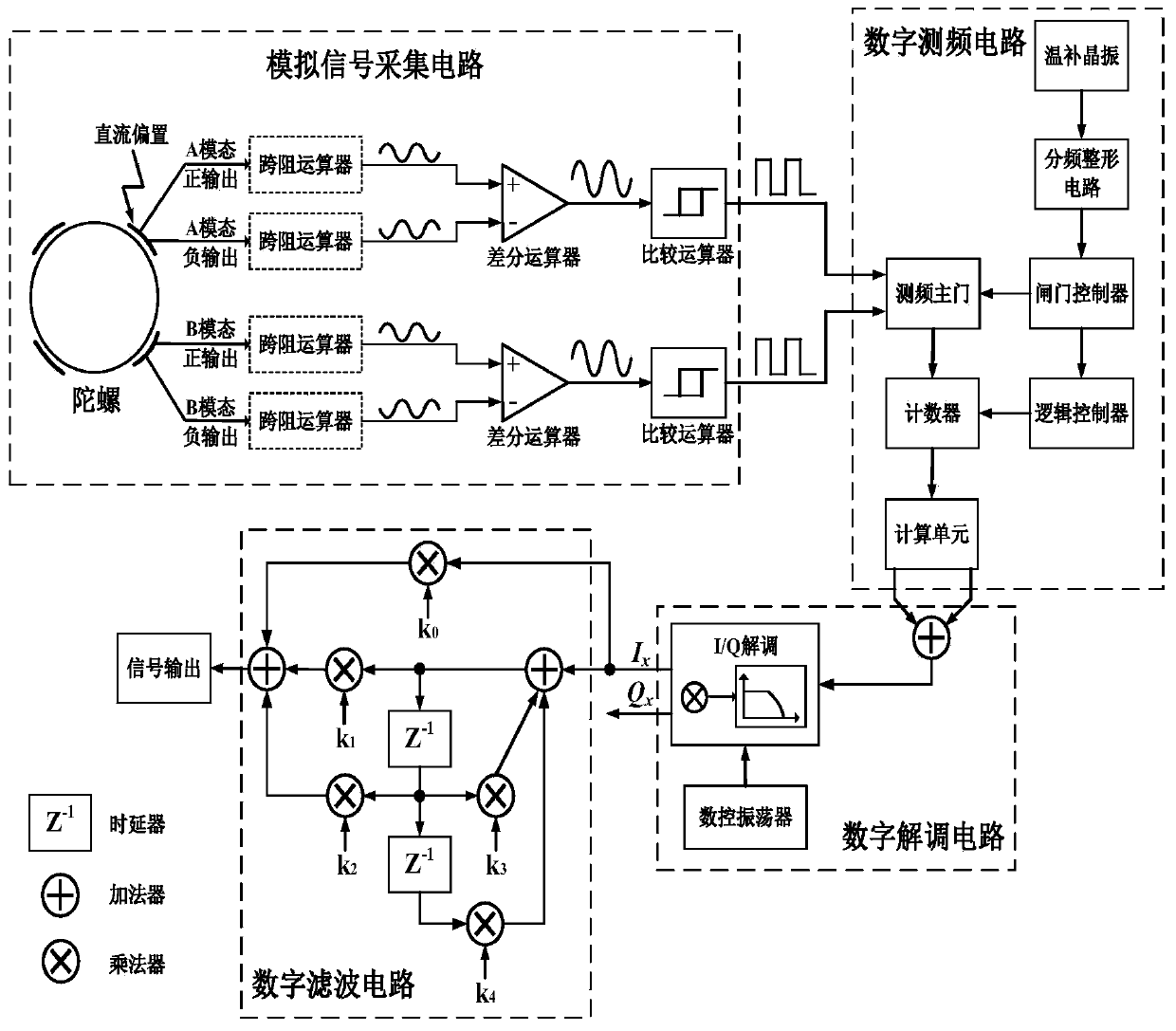
[0091] Such as figure 1 As shown, Embodiment 1 of the present invention describes a differential band-pass FM MEMS gyroscope rate analysis device, which includes an analog circuit part and a digital circuit part. in:

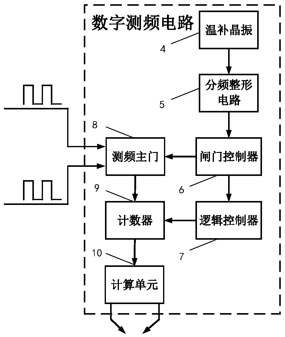
[0092] The invention puts devices such as crystal oscillators that are prone to electromagnetic interference in the digital circuit, thereby effectively isolating the digital circuit and the analog circuit, avoiding electromagnetic interference from affecting the analog signal, and enhancing the electromagnetic compatibility of the system.

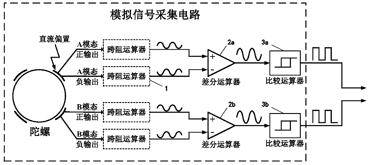
[0093] Specifically, the analog circuit part is an analog signal acquisition circuit for acquiring signals of the MEMS gyroscope. The digital circuit part includes digital signal frequency measurement circuit, digital signal demodulation circuit and digital signal filter circuit.

[0094] The digital circuit part is used to complete the analysis and processing of MEMS gyroscope signals such as frequency measurement, demodu...

Embodiment 2

[0207] Embodiment 2 of the present invention describes a differential band-pass frequency modulation MEMS gyroscope rate analysis method, which is based on the differential band-pass frequency modulation MEMS gyroscope rate analysis device mentioned in the above-mentioned embodiment 1.

[0208] Such as Figure 8 As shown, a differential band-pass frequency modulation MEMS gyroscope rate analysis method includes the following steps:

[0209] The two vibration modes of the gyroscope respectively output four sine wave signals in the form of differential signals.

[0210] Among them, there are two sine wave signals which are the positive output signal of the first vibration mode and the negative output signal of the first vibration mode, and two sine wave signals are the positive output signal of the second vibration mode and the negative output signal of the second vibration mode. state of the negative output signal.

[0211] The above four channels of sine wave signals are res...


PUM


Abstract

The invention belongs to the technical field of gyroscope signal processing and particularly discloses a differential band-pass frequency modulation MEMS gyroscope rate analysis device and method. Thedevice comprises an analog circuit part and a digital circuit part. And the analog circuit part is used for realizing analog signal acquisition of an MEMS gyroscope. And the digital circuit part comprises a digital signal frequency measurement circuit, a digital signal demodulation circuit and a digital signal filter circuit. The digital circuit part is mainly used for completing frequency measurement, demodulation, filtering and other processing of MEMS gyroscope signals. According to the invention, the rate analysis of the MEMS gyroscope is completed in the digital circuit such that a largenumber of crystal oscillator signals can be effectively prevented from being introduced into an analog circuit area, and the device is ensured to have good electromagnetic compatibility. And meanwhile, due to the characteristic that the digital circuit is not easily influenced by the environment, the gyroscope angular rate can still be accurately analyzed in an extreme environment. In addition, the signal-to-noise ratio of the device is improved.

Description

technical field [0001] The invention belongs to the technical field of gyroscope signal processing, and in particular relates to a differential band-pass frequency modulation MEMS gyroscope rate analysis device and a differential band-pass frequency modulation MEMS gyroscope rate analysis method. Background technique [0002] The gyroscope is the core device of the inertial navigation system. In recent years, amplitude-modulated MEMS gyroscopes have been widely used in consumer electronics, industrial manufacturing, and military fields, but their navigation accuracy still has huge room for improvement. As we all know, the long-term operation of the MEMS gyroscope and the output drift of the MEMS gyroscope affected by the ambient temperature have always been the key issues affecting its navigation accuracy. How to further improve the long-term stability of MEMS gyroscopes in a full-temperature environment has always been a problem that plagues the industry. For the periodic...

Claims


Application Information

Patent Timeline
IPC IPC(8): G01C25/00
CPCG01C25/00
Inventor 李崇王雨晨侯佳坤
Owner OCEAN UNIV OF CHINA
Why Eureka
Try Eureka