A kind of preparation method of oct catheter tip

A catheter tip and distal technology, which is applied in the field of OCT catheter tip preparation, can solve the problems of increasing the risk of unfavorable blood vessels, increasing the risk of unfavorable blood, and unsmooth end surfaces, etc., achieving easy operation of the preparation method, winning operation time, and tip hardness Reduced effect

Active Publication Date: 2022-05-24
WUHAN AGESI TECH CO LTD
View PDF6 Cites 0 Cited by
  • Summary
  • Abstract
  • Description
  • Claims
  • Application Information

AI Technical Summary

Problems solved by technology

[0004] This method has the following disadvantages: Since the tip is in direct contact with human blood, UV glue will increase the risk of adverse effects on blood
In addition, since the tip is cured by two kinds of tubing with ultraviolet glue, the tip will be very hard, and the end surface will not be round, which will increase the risk of adverse effects on blood vessels

Method used


Image

  • A kind of preparation method of oct catheter tip
  • A kind of preparation method of oct catheter tip
  • A kind of preparation method of oct catheter tip

Examples


preparation example Construction

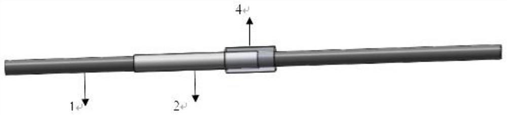
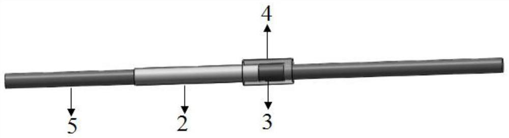
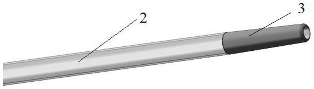
[0030] refer to Figure 1-Figure 3 As shown, the present application provides a method for preparing an OCT catheter tip, comprising the following steps:

[0031] Step 1: preprocessing, heat shrinking the diameter of one end of the imaging window tube 2 to a preset value;

[0032] Step 2: Welding integration, welding the heat-shrinked end of the imaging window tube 2 and the distal marking tube 3 into one body.

[0033] The diameter of one end of the imaging window tube 2 is heat-shrinked to be consistent with the diameter of the distal marking tube 3 by pre-processing, and then the end of the pre-processed imaging window tube 2 is welded to the distal marking tube. 3. The welding is integrated, and the inner wall of the butt joint is guaranteed to have a consistent and smooth diameter after welding, so that the OCT catheter tip can be smoothly carried out when inserting or withdrawing the guide wire, which greatly saves the operation time and reduces the possible risks of th...

Embodiment 1

[0050] Set the imaging window tube on the first mandrel (the length of the first mandrel is twice the length of the imaging window tube), and then set the heat shrinkable tube on the to-be-treated end and the first mandrel of the imaging window tube. On a mandrel, the imaging window tube and the first mandrel section covered with the heat shrinkable tube are placed in the mold hole of the heat welding machine for heating, the heating temperature is 190°C, and the heating time is 5s. The heat-shrinkable tube shrinks and transfers heat to the imaging window tube, so that the inner diameter of the end of the imaging window tube sleeved with the heat-shrinkable tube is the same as the diameter of the first mandrel, and finally the heat-shrinkable tube and the first mandrel are removed. Mandrel.

[0051] Both the pretreated imaging window tube and the distal end marker tube are sleeved on the second mandrel, the end face of the distal end marker tube is connected to the pretreated ...


PUM

PropertyMeasurementUnit
thicknessaaaaaaaaaa
diameteraaaaaaaaaa
diameteraaaaaaaaaa

Abstract

The present application discloses a method for preparing the tip of an OCT catheter, which includes the following steps: pretreatment, heat-shrinking the diameter of one end of the imaging window tube to a preset value; welding for integration, and heat-shrinking the end of the imaging window tube It is welded together with the distal identification tube. The present application provides a method for preparing the tip of an OCT catheter. The diameter of one end of the imaging window tube is heat-shrunk to be consistent with the diameter of the distal marking tube through pretreatment, and then the pretreated imaging window tube is welded The end part is integrated with the distal marker tube by welding, and at the same time, after welding, the diameter of the inner wall of the butt joint is guaranteed to be consistent and smooth, so that the tip of the OCT catheter can be smoothly inserted or withdrawn from the guide wire, which greatly saves the operation time and reduces the operation time. possible risks.

Description

technical field [0001] The present application relates to the technical field of optical interference tomography, in particular to a method for preparing a tip of an OCT catheter. Background technique [0002] Optical Coherence Tomography (OCT) technology is a new type of biomedical optical imaging method, through an endoscopic imaging catheter, it can provide high-resolution images of blood vessel cross-section (axial resolution 5-10μm). , lateral resolution 20-40 μm). The optical imaging probe is a key component of the endoscopic imaging catheter, and its optical performance directly affects imaging indicators such as image resolution, imaging depth, and contrast. In order to realize the clear scanning of stenotic tissues in the human body by OCT, it is necessary to ensure that the imaging probe can smoothly pass through the curved stenotic lesions and rotate to scan. Therefore, the technical difficulty is the miniaturization of the OCT endoscopic imaging probe. [0003]...

Claims


Application Information

Patent Timeline
Patent Type & Authority Patents(China)
IPC IPC(8): B29C65/00B29C65/02B29C61/02A61B1/00A61B5/00
CPCB29C65/02B29C66/02B29C66/5221B29C61/025A61B5/0066A61B1/00154
Inventor 符钰棋居文彬
Owner WUHAN AGESI TECH CO LTD
Why Eureka
Try Eureka